Two-way throttle valve and pantograph air supply control system formed by same

A two-way throttling valve and pantograph technology, which is applied in the direction of valve housing structure, valve operation/release device, lift valve, etc., can solve the problems of large space occupation, unreasonable design, inconvenient maintenance, etc., and achieve simple structure, Avoid too fast action and avoid the effect of excessive transient

Pending Publication Date: 2020-09-18
CRRC ZIYANG CO LTD
View PDF0 Cites 0 Cited by
  • Summary
  • Abstract
  • Description
  • Claims
  • Application Information

AI Technical Summary

Problems solved by technology

In the process of controlling the lifting and lowering of the pantograph, the existing technology adopts a pneumatic control system or a hydraulic control system, and controls by setting up two sets of throttle valve devices for raising the bow and lowering the bow, which leads to a complex structure of the whole control system and takes up a lot of space. Large, resulting in inconvenience for later maintenance
[0003] Therefore, the existing pantograph lifting control system has an unreasonable design, which needs to be improved and optimized to obtain a more reasonable technical solution and solve the deficiencies in the existing technology

Method used


Image

  • Two-way throttle valve and pantograph air supply control system formed by same
  • Two-way throttle valve and pantograph air supply control system formed by same
  • Two-way throttle valve and pantograph air supply control system formed by same

Examples


Embodiment 1

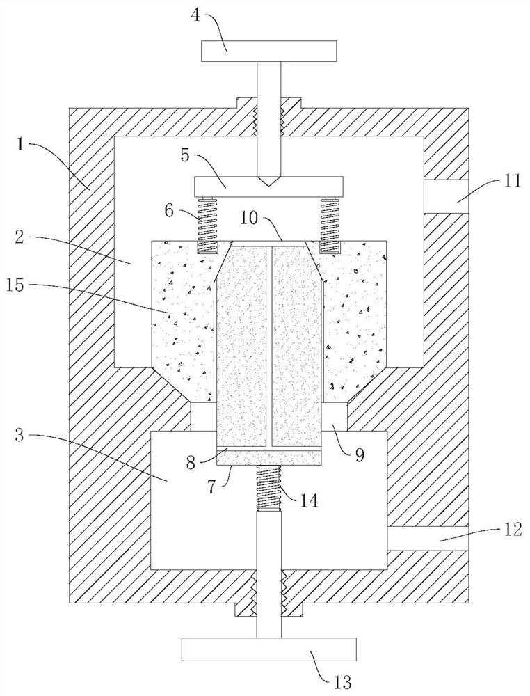
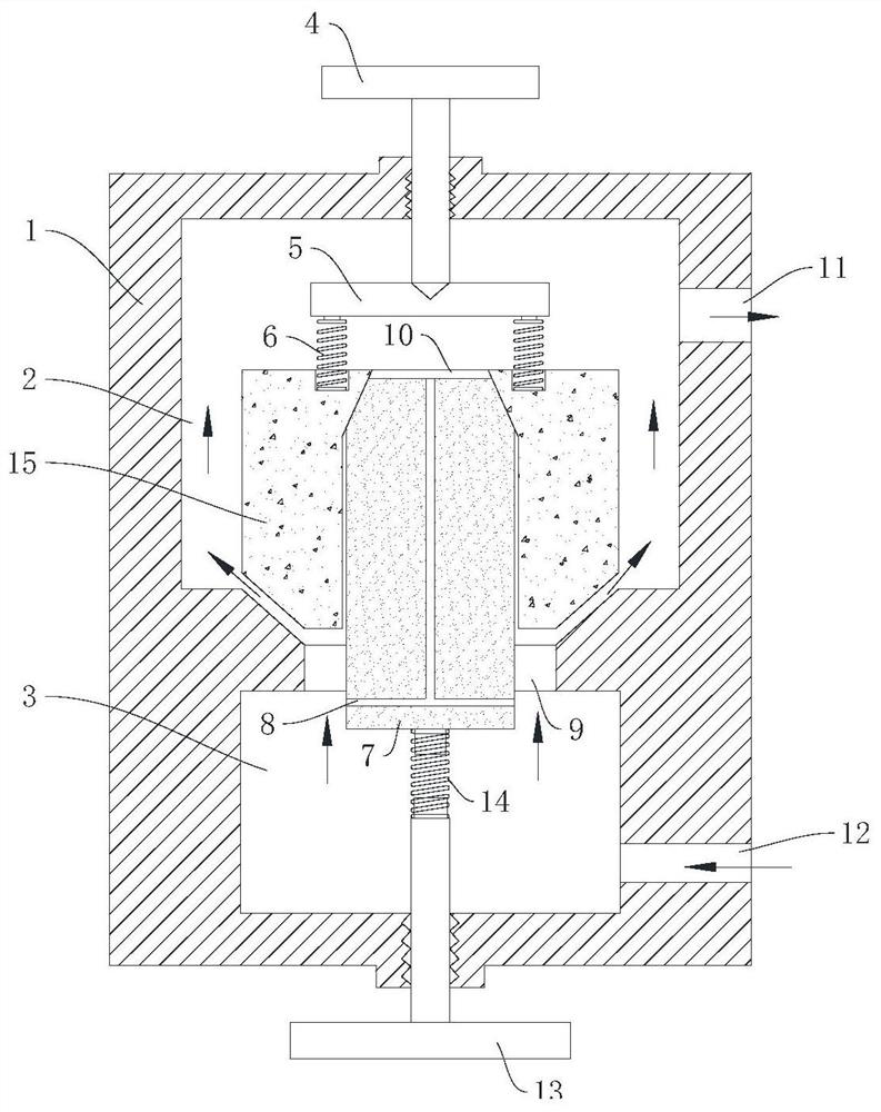
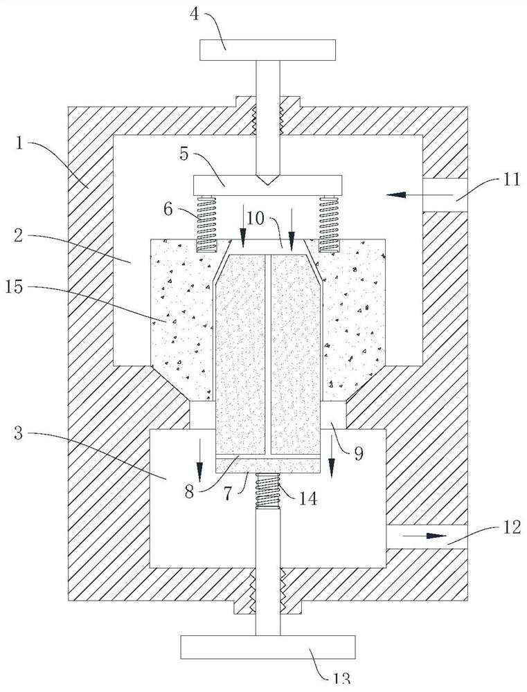
[0033] Such as figure 1 As shown, this embodiment mainly solves the structural optimization of the throttle valve. The existing throttle valve is generally a one-way throttling valve. And avoid excessive pressure transients of the fluid pressure medium.

[0034]The specific scheme adopted is: a two-way throttle valve, including a valve body 1 and a valve core, the valve body 1 is provided with a first chamber 2 communicating with the pressure medium and a second chamber 3 communicating with the actuator, A communication port 9 is provided between the first chamber 2 and the second chamber 3. The valve core includes an outer core 15 and an inner core 7 that are nested, and the outer core 15 is inside the first chamber 2. Sliding and used to open and close the communication port 9, the first chamber 2 is provided with a first elastic component for pressing against the outer core 15 and making the outer core 15 close the communication port 9; the outer core 15 is provided with a...

Embodiment 2

[0050] The above-mentioned embodiment discloses the technical solution of the two-way throttle valve, and this embodiment provides a technical solution for applying the two-way throttle valve to the pantograph air supply control system, specifically as follows:

[0051] Such as Figure 5 As shown, a pantograph air supply control system integrating a two-way throttle valve adopts the two-way throttle valve described in Embodiment 1, and the first chamber 2 of the two-way throttle valve communicates with the air duct of the pantograph , the second chamber 3 is sequentially communicated with the electromagnetic control valve 17, the pressure reducing valve 16 and the gas source.

[0052] The electromagnetic control valve 17 adopts a two-position three-way electromagnetic valve. Among them, one working position of the solenoid valve is connected to the gas source and the two-way throttle valve, and the gas medium from the gas source is sent to the second chamber 3 to help the pan...


PUM


Abstract

The invention relates to the technical field of power control, specifically relates to a structure of an air pressure valve and a hydraulic valve, and particularly relates to a two-way throttle valveand a pantograph air supply control system formed by the same. The two-way throttle valve comprises a valve body and a valve element, wherein a first chamber and a second chamber are arranged in the valve body; a communication port is formed between the first chamber and the second chamber; the valve element comprises an outer core and an inner core which are arranged in a nested mode; the outer core slides in the first chamber and is used for opening and closing the communication port; a pressure relief opening is formed in the outer core, and the inner core is in sliding fit with the outer core and is used for opening and closing the pressure relief opening; and a first elastic assembly used for abutting against the outer core is arranged in the first chamber, and a second elastic assembly used for abutting against the inner core is arranged in the second chamber. The air supply control system adopts the two-way throttle valve, the structure is simpler, the pantograph ascending and descending operation of a pantograph can be realized only by adopting one throttle valve, the operation is simple, and the efficiency is higher.

Description

technical field [0001] The invention relates to the technical field of power control, in particular to the structure of a pneumatic valve and a hydraulic valve, and in particular to a two-way throttle valve and a pantograph air supply control system formed therefrom. Background technique [0002] The electric traction locomotive obtains electric energy from the catenary and uses it as the driving energy, mainly through the pantograph; after the pantograph rises, it approaches the catenary and obtains electric energy, and when it falls, it moves away from the catenary and stops obtaining electric energy. In the process of controlling the lifting and lowering of the pantograph, the existing technology adopts a pneumatic control system or a hydraulic control system, and controls by setting up two sets of throttle valve devices for raising the bow and lowering the bow, which leads to a complex structure of the whole control system and takes up a lot of space. Large, resulting in...

Claims


Application Information

Patent Timeline
Patent Type & Authority Applications(China)
IPC IPC(8): F16K1/00F16K1/32F16K1/44F16K27/02F16K31/12F15B13/02B60L5/32
CPCB60L5/32F15B13/021F16K1/00F16K1/32F16K1/443F16K27/0254F16K31/12Y02T90/16
Inventor 李海超郝翰张斌姜葛孙川肖阳华华利
Owner CRRC ZIYANG CO LTD
Why Eureka
Try Eureka