
Elevator traction device

An elevator traction and traction technology, which is applied in the field of elevator traction devices, can solve the problems of short service life of parts, jamming, and high maintenance frequency, and achieve the effects of convenient operation and improved stability.

Active Publication Date: 2018-03-09
平湖市中劢磁业股份有限公司
View PDF6 Cites 0 Cited by
  • Summary
  • Abstract
  • Description
  • Claims
  • Application Information

AI Technical Summary

Problems solved by technology

As a special equipment, the safety of the elevator is directly related to the life safety of passengers. Therefore, the requirements for elevator repair and maintenance are high, that is, the frequency of maintenance is high, the service life of parts is short, and the replacement of vulnerable parts High frequency
And the elevator needs to lock the car and the counterweight during the maintenance process, so as to facilitate the loosening of the traction wire rope, and realize the inspection or replacement of the guide wheels of each component. In the elevator maintenance of the prior art, the guide wheels After the maintenance or replacement is completed, when the traction wire rope is reset, there is a risk of misalignment between the traction wire rope and the guide wheel, that is, the traction wire rope slips from the guide wheel, thereby causing the shaft of the traction wire rope and the guide wheel to be stuck, or As a result, the rotating shaft of the guide wheel is constantly rubbed against the traction wire rope, resulting in premature damage to both parts

Method used


Image

  • Elevator traction device
  • Elevator traction device
  • Elevator traction device

Examples


Embodiment Construction

[0017] The present invention will be further described below in conjunction with the accompanying drawings and specific embodiments.

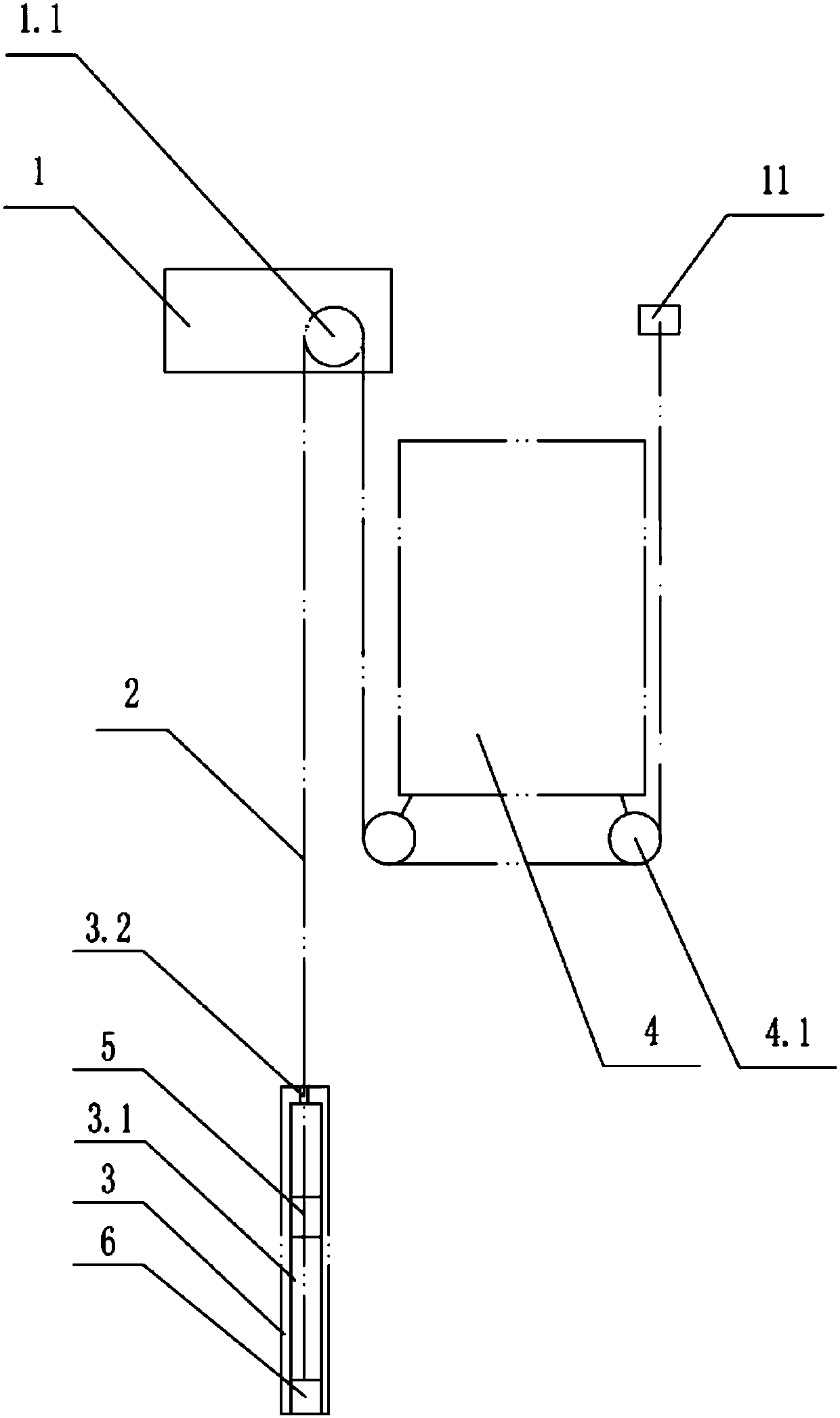
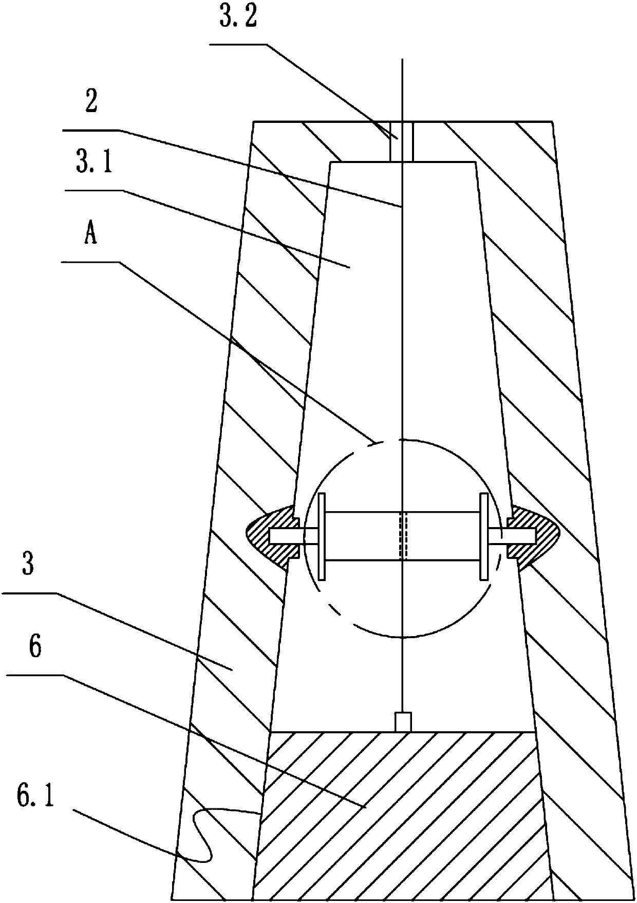
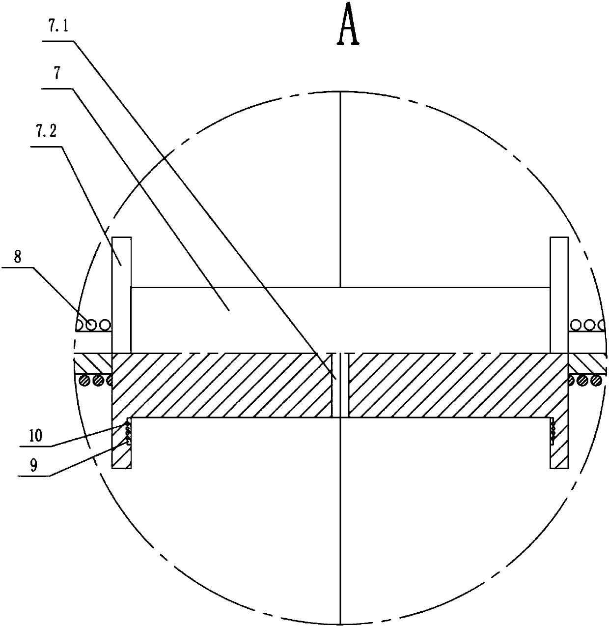
[0018] The invention provides an elevator traction device, which includes a traction machine 1 installed in the elevator shaft, a traction wire rope 2 and a counterweight 3 arranged under the traction machine 1, and is characterized in that: the traction wire rope 2 One end is fixed to the inner wall of the elevator shaft, and the other end of the traction wire rope 2 encircles the guide wheel 4.1 at the bottom of the car 4 and the driving wheel 1.1 on the traction machine 1 in sequence along its own length, and is fixed with the counterweight 3. The above-mentioned counterweight 3 is provided with an automatic winding mechanism 5 for winding the traction wire rope 2 until the traction wire rope 1 is in a tight state.

[0019] As preferably, one end of the traction wire rope 2 is fixed to the car rope head plate 11, and the car rope head plate ...


PUM


Abstract

The invention discloses an elevator traction device which comprises a tractor (1), a traction steel rope (2) and a counterweight filler weight (3). The tractor (1) is mounted in an elevator well hole. The counterweight filler weight (3) is arranged below the tractor (1). The elevator traction device is characterized in that one end of the traction steel rope (2) is fixed on the inner wall of the elevator well hole. The other end of the traction steel rope (2) surrounds guide wheels (4.1) at the bottom of a car platform sill (4) and a driving wheel (1.1) on the tractor (1) in sequence in the self length direction, and is fixed to the counterweight filler weight (3). An automatic winding mechanism (5) used for winding the traction steel rope (2) till the traction steel rope (2) is in the tightened state is arranged in the counterweight filler weight (3). According to the elevator traction device, provided by the invention, during the elevator traction process, when the car platform sill and the counterweight filler weight do not apply an acting force on the traction steel rope, the traction steel rope is enabled not to be loosened from the guide wheels. The risk that the traction steel rope is loosened from the guide wheels is avoided.

Description

technical field [0001] The invention relates to the technical field of elevators, in particular to an elevator traction device. Background technique [0002] The lifting process of the elevator is to wind the driving wheel of the traction machine, the guide wheel of the car and the counterweight wheel of the counterweight in sequence through the traction wire rope, so as to drive the movement of the car through the friction between the driving wheel and the traction wire rope. lift. As a special equipment, the safety of the elevator is directly related to the life safety of passengers. Therefore, the requirements for elevator repair and maintenance are high, that is, the frequency of maintenance is high, the service life of parts is short, and the replacement of vulnerable parts High frequency. And the elevator needs to lock the car and the counterweight during the maintenance process, so as to facilitate the loosening of the traction wire rope, and realize the inspection ...

Claims


Application Information

Patent Timeline
Patent Type & Authority Patents(China)
IPC IPC(8): B66B11/04B66B7/06
CPCB66B7/06B66B7/068B66B11/04
Inventor 袁陆峰曹诗晴
Owner 平湖市中劢磁业股份有限公司
Learn More