Water-sand separation structures suitable for straight-line steep channel spillways

A technology of water and sand separation and spillway, applied in the field of sand removal, can solve the problems of few water and sand separation measures, small probability of large particles and loose particles, etc.

Inactive Publication Date: 2017-12-15
SICHUAN UNIV
View PDF9 Cites 0 Cited by
  • Summary
  • Abstract
  • Description
  • Claims
  • Application Information

AI Technical Summary

Problems solved by technology

[0004] However, all the above-mentioned grit chambers are aimed at the suspended and fine particles in the water flow, and their design is mainly based on the principle of water and sand separation such as spiral flow in bends, sand settling and regular sand discharge at the bottom, and such buildings The probability of large particles and granular bodies appearing in the medium is relatively small
However, there are relatively few water-sediment separation measures for the sediment-laden flow containing large particles and loose-grained sediment in the spillway of the steep channel
However, in actual engineering, there are many examples of damage to the overflow boundary of steep channel spillways caused by high-speed, high-sediment flow containing large particles and granular sediment, and many similar projects require regular post-flood repairs

Method used


Image

  • Water-sand separation structures suitable for straight-line steep channel spillways
  • Water-sand separation structures suitable for straight-line steep channel spillways
  • Water-sand separation structures suitable for straight-line steep channel spillways

Examples


Embodiment Construction

[0068] The implementation examples of the present invention are given below in conjunction with the accompanying drawings, and the present invention will be further described through the examples. It is necessary to specify here that the specific implementation of the present invention is not limited to the forms in the examples. According to the disclosed content of the present invention, those skilled in the art can also implement in other specific ways. Therefore, the examples It should not be understood as a specific embodiment that the present invention can only implement.

[0069] Engineering example

[0070] The example of this project is the flood drainage system of a construction stockyard of a hydropower station. The stockyard is located in a debris flow ditch. The upstream of the stockyard uses a retaining dam to intercept the upstream flow and sand, and a drainage tunnel is used in front of the retaining dam. The sand is guided to a suitable location, and then rel...


PUM


Abstract

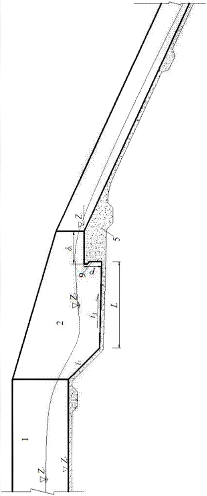
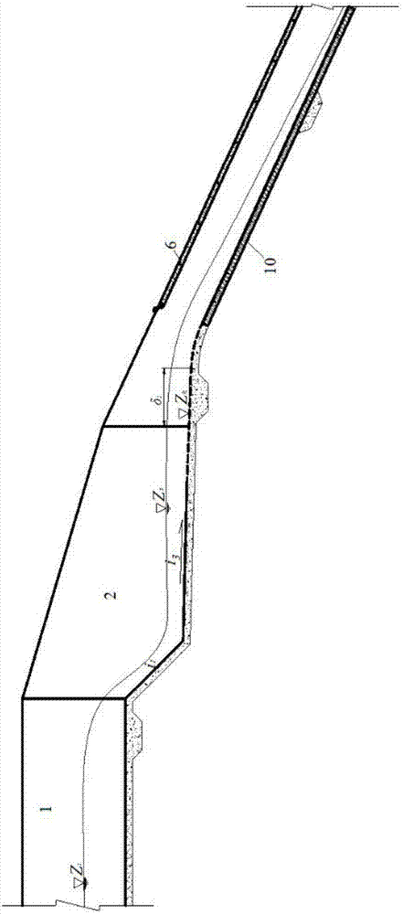
The invention discloses a water-sand separation building applicable to a linear chute spillway. The water-sand separation building mainly comprises a sand collection pool of which the upstream end is connected with an incoming flow spillway, and a flow pass channel and a sand discharge channel which are positioned at the downstream part of the sand collection pool and are arranged side by side, wherein an inlet of the sand discharge channel is in smooth connection with the sand collection pool; the flow pass channel is connected with the sand collection pool through an overflow weir; the water attaining surface of the overflow weir is an circular arc surface, and forms a sand guide wall used for introducing large-particle and granular sediment in a water current into the sand discharge channel; the upstream end of the circular arc surface of the sand guide wall is connected with the side wall on the outer side of the flow pass channel; the downstream end of the circular arc surface of the sand guide wall is connected with a separation side wall of the flow pass channel and the sand discharge channel; and the pool bottom of the sand collection pool in front of the sand guide wall has a gradient inclined to the inlet of the sand discharge channel. Through the adoption of the water-sand separation building, the large-particle and granular sediment in a high-sand content water current in a chute can be separated from the water current relatively well, the sediment which has relatively large harm to the chute spillway is discharged from the special sand discharge channel, and the purposes that the protection range is decreased and the safety of project operation is improved are achieved.

Description

technical field [0001] The invention relates to a sand discharge technology in water conservancy and hydropower projects and disaster prevention and reduction projects, in particular to a water and sand separation structure suitable for spillways in linear steep grooves. Background technique [0002] In water conservancy and hydropower projects or disaster prevention and mitigation projects, the drainage facilities of hydraulic structures such as slag yards, retaining dams, tailings ponds, etc. usually use steep groove spillways. In addition to flood discharge during flood seasons, the steep groove spillway also has the function of sand discharge effect. Because the sediment involved in this type of retaining structure has the characteristics of wide particle size gradation, large particle size and large particle content. Studies have shown that in similar steep channel spillways, a large amount of coarse-grained sediment and granular bodies carried by high-speed water flow...

Claims


Application Information

Patent Timeline
Patent Type & Authority Patents(China)
IPC IPC(8): E02B8/06
CPCE02B8/06
Inventor 马旭东聂锐华邓军刘兴年
Owner SICHUAN UNIV
Why Eureka
Try Eureka