

Fault information detection method and electronic device
A technology of electronic equipment and detection methods, applied in the direction of error detection/correction, electrical digital data processing, instruments, etc., can solve the problems of electronic equipment damage, ME chip not locked, impact, etc., to achieve the effect of reducing complexity and solving problems
- Summary
- Abstract
- Description
- Claims
- Application Information
AI Technical Summary
Problems solved by technology
Method used
Image

Examples
Embodiment Construction
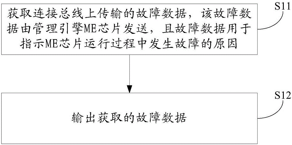
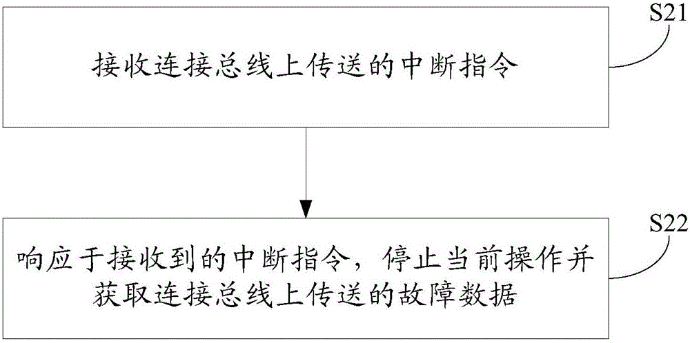
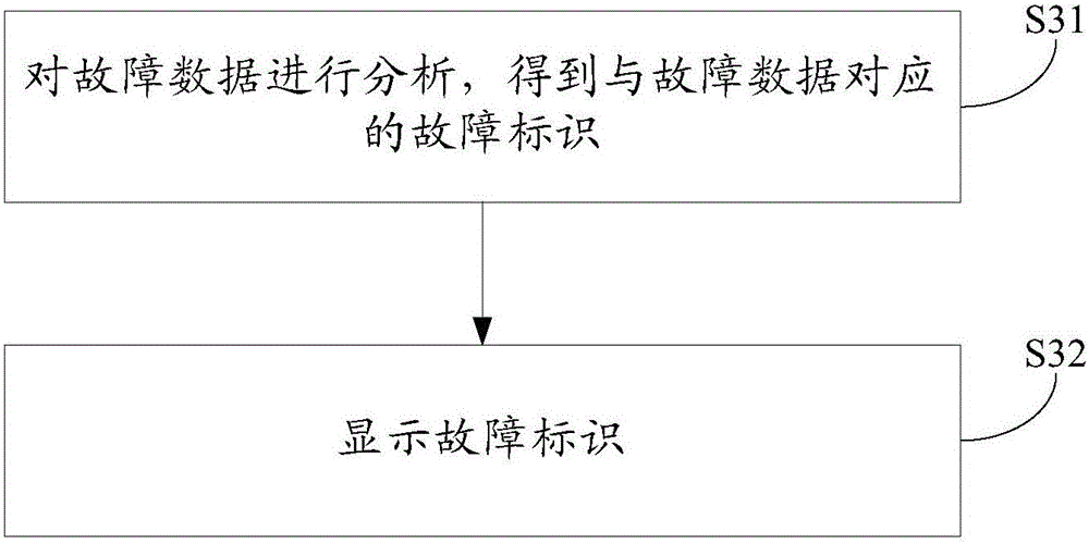
[0035] The following will clearly and completely describe the technical solutions in the embodiments of the present invention with reference to the accompanying drawings in the embodiments of the present invention. Obviously, the described embodiments are only some, not all, embodiments of the present invention. Based on the embodiments of the present invention, all other embodiments obtained by persons of ordinary skill in the art without making creative efforts belong to the protection scope of the present invention.
[0036] The invention is applicable to numerous general purpose or special purpose computing device environments or configurations. For example: desktops, notebooks, tablet computers and other electronic devices with management engine (Management Engine, ME) chip, wherein the management engine chip can be integrated in the south bridge chip of the electronic device.
[0037] see figure 1 , figure 1 An implementation flowchart of the fault information detectio...
PUM
 Abstract
Description
Claims
Application Information