Detection method and detection system for film thickness abnormality
A detection method and detection system technology, which is applied to the authenticity inspection of banknotes, instruments, handling coins or valuable banknotes, etc., can solve problems such as abnormality and inability to accurately determine the thickness, and achieve the effect of accurate detection
- Summary
- Abstract
- Description
- Claims
- Application Information
AI Technical Summary
Problems solved by technology
Method used
Image

Examples
Embodiment 1
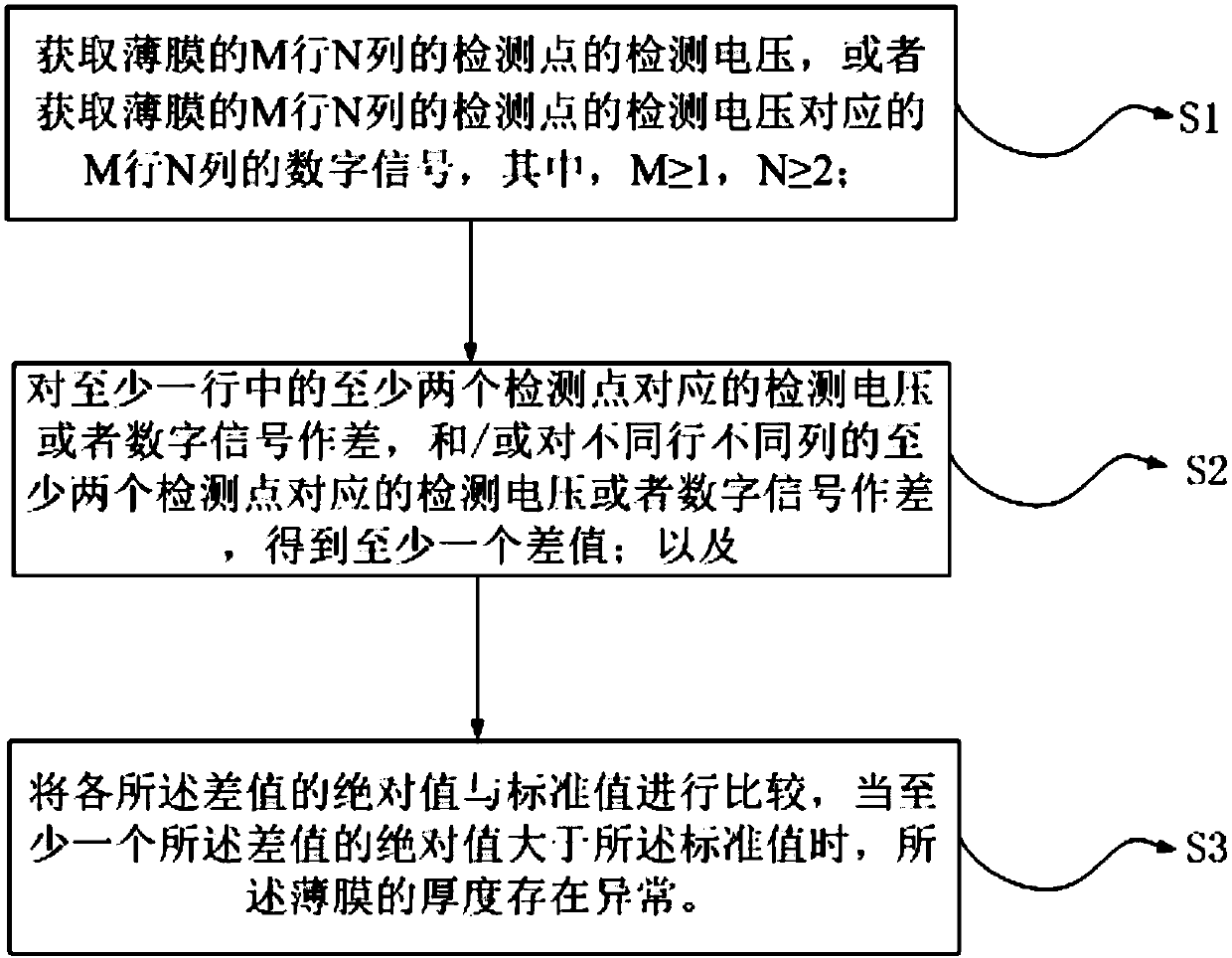
[0051] use Image 6 The detection system detects the thickness of the film. The detection unit is a thickness sensor composed of a row of thickness chips to detect the thickness of the object and output the corresponding voltage value. The calculation unit is a DSP processor and the storage unit is a DRAM memory. The thickness sensor has five detection electrodes, which scan three rows of banknotes, that is, the detection points of three rows and five columns on the banknote ( figure 2 Two rows of detection points 100) are shown for detection, and detection voltages of three rows and five columns are obtained. Use analog-to-digital conversion unit to convert these detection voltages into digital signals P Y , Using the formula P Y -P (Y+1) Calculate the difference between the digital signals corresponding to the two adjacent detection points in each row. For example, the first row of digital signals is P in turn 1 , P 2 , P 3 , P 4 , P 5 , Make the difference of the correspondin...
Embodiment 2
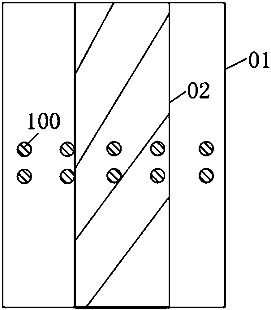
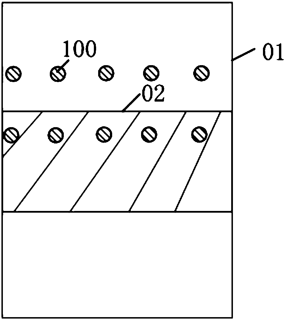
[0055] The thickness of the film is detected by the same detection system as in Embodiment 1. It is also assumed that the thickness sensor has five detection electrodes in total and scans three rows. The digital signals of the detection points in the first row are sequentially P 11 , P 12 , P 13 , P 14 , P 15 ; The digital signal corresponding to the detection point in the second row is P 21 , P 22 , P 23 , P 24 , P 25 ; The digital signal corresponding to the detection point in the third row is P 31 , P 32 , P 33 , P 34 , P 35 ,among them figure 2 , image 3 , Figure 4 Two rows of detection points 100 are shown in.
[0056] Using formula P XZ -P (X+1)(Z+1) Calculate the difference between the digital signals corresponding to the two detection points in two adjacent rows and two adjacent columns, and the calculated result of the difference between the first row and the second row is P 11 -P 22 , P 12 -P 23 , P 13 -P 24 , P 14 -P 25 ; The difference between the second row and the...
Embodiment 3
[0059] The difference from embodiment 2 is that the formula P X(Z+1) -P (X+1)Z Calculate the difference of the digital signals corresponding to the two detection points in two adjacent rows and adjacent columns, and the calculated result of the difference between the first row and the second row is P 12 -P 21 , P 13 -P 22 , P 14 -P 23 , P 15 -P 24 ; The difference between the second row and the third row is P 22 -P 31 , P 23 -P 32 , P 24 -P 33 , P 25 -P 34 , figure 2 , image 3 or Figure 5 Two rows of detection points 100 are shown.
[0060] Comparing the above-mentioned difference result with the standard value, it is found that some of the difference result is larger than the standard value, and the shape of the foreign body can be judged as figure 2 , image 3 or Figure 5 .
PUM
 Abstract
Description
Claims
Application Information