
An angle alarm device for electronic fence

A technology of an alarm device and an electronic fence, applied in the electronic field, can solve the problems of being easily disturbed by the external environment, having a short lifespan, and low measurement accuracy.

Active Publication Date: 2018-06-26
SHANGHAI FRUKTBARE LANDET ELECTRONICS SCI & TECH
View PDF5 Cites 0 Cited by
  • Summary
  • Abstract
  • Description
  • Claims
  • Application Information

AI Technical Summary

Problems solved by technology

[0009] In view of the shortcomings of the above-mentioned prior art, the purpose of the present invention is to provide a non-contact angle alarm device for electronic fences with good water resistance, high measurement accuracy, long life, easy installation, and strong anti-interference ability to solve the current problems. There are problems such as poor water resistance, low measurement accuracy, short life, and susceptibility to external environment interference in the resistance strain gauge pressure sensor.

Method used


Image

  • An angle alarm device for electronic fence
  • An angle alarm device for electronic fence
  • An angle alarm device for electronic fence

Examples


Embodiment Construction

[0033] In order to make the purpose, technical solutions and advantages of the embodiments of the present invention more clear, the technical solutions in the embodiments of the present invention will be clearly and completely described below in conjunction with the drawings in the embodiments of the present invention. Apparently, the described embodiments are some, but not all, embodiments of the present invention. Based on the embodiments of the present invention, all other embodiments obtained by persons of ordinary skill in the art without creative efforts fall within the protection scope of the present invention.

[0034] The present invention will be further described in detail below in conjunction with the accompanying drawings.

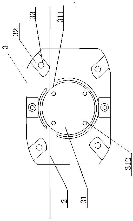
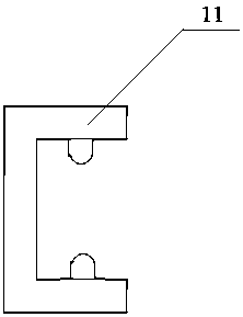
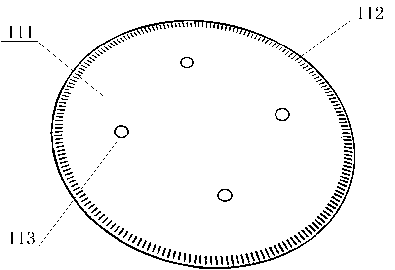
[0035] like figure 1 As shown, the present invention provides an angle alarm device for electronic fences, including: a tension wire 2, a housing 3, and a rotating wheel 31 placed in the center of the housing, and the corners of the housing p...


PUM


Abstract

The invention relates to a rotation position alarm device. The rotation position alarm device comprises a sensor, a pull line, a shell and a rotation wheel arranged in the center of the shell. The side wall of the rotation wheel is provided with a groove for winding the pull line. The pull line is led out from the rotation wheel and wound around the rotation wheel by at least one round and then penetrates out from the two sides of the shell. The sensor is arranged above the rotation wheel space and is not in direct contact with the rotation wheel. Specifically, when the pull line is subjected to outside pull force, the rotation wheel is driven to rotate and move, the sensor detects the angle change signal of the rotation wheel and converts the angle change signal into an electric signal to be output, and an alarm prompt is sent out. The sensor in the rotation position alarm device has no contact point and is long in service life; by means of non-contact detection, damages to the sensor and an object to be detected are avoided, stable detection can be carried out even under a harsh environment where water or oil splashing exists, the reaction speed is high, and installation is flexible.

Description

technical field [0001] The invention relates to the field of electronic technology, in particular to an angle alarm device for an electronic fence applied in a tension fence alarm system. Background technique [0002] The tension fence alarm device is provided with a sensor, and when an intruder pulls the steel wire connected to the fence, the sensor outputs an electric signal to the control center, and the control center gives an alarm immediately after receiving the output signal. In the prior art, the sensors of the tension fence alarm device all adopt resistance strain gauge pressure sensors. When an intrusion occurs on the protected site, that is, when the intruder generates a pulling force on the fence, the pulling force is transmitted to the tension fence alarm device through the steel wire rope. When the sensor of the tension fence alarm device senses the force change on the wire rope, the resistance strain gauge pressure sensor works. The resistance of the resista...

Claims


Application Information

Patent Timeline
Patent Type & Authority Patents(China)
IPC IPC(8): G08B13/12
CPCG08B13/122
Inventor 周毅朱新培
Owner SHANGHAI FRUKTBARE LANDET ELECTRONICS SCI & TECH
Learn More