Circulating device of electric vehicle battery thermal management system and control method of circulating device

A technology for battery thermal management and electric vehicles, applied to secondary batteries, circuits, electrical components, etc., can solve problems such as reduced output power, single battery cooling method, power system failure, etc., achieve a wide range of ambient temperature, and ensure cold start Requirements, the effect of high temperature control accuracy

Active Publication Date: 2016-10-12
WUHAN UNIV OF TECH
View PDF7 Cites 14 Cited by
  • Summary
  • Abstract
  • Description
  • Claims
  • Application Information

AI Technical Summary

Problems solved by technology

Lithium-ion batteries are widely used in electric vehicles due to their superior performance. Its optimal operating temperature range is between 20 degrees and 40 degrees. However, lithium-ion batteries generate heat during operation. If they are not dissipated in time, it is easy to It causes heat accumulation inside the battery. When the ambient temperature is high, the maximum temperature inside the battery pack can exceed 60 degrees, which may lead to failure of the power system or even a safety accident. At the same time, the impact of low ambient temperature on the internal resistance of the battery cannot be ignored. Especially the ohmic internal resistance, low temperature will increase the internal resistance of the battery and reduce the output power
The existing electric vehicle battery cooling method is single, and each system lacks a combined thermal management solution, resulting in low efficiency

Method used


Image

  • Circulating device of electric vehicle battery thermal management system and control method of circulating device
  • Circulating device of electric vehicle battery thermal management system and control method of circulating device
  • Circulating device of electric vehicle battery thermal management system and control method of circulating device

Examples


Embodiment Construction

[0026] The technical solutions of the present invention will be described below in conjunction with the accompanying drawings and embodiments.

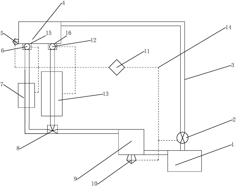
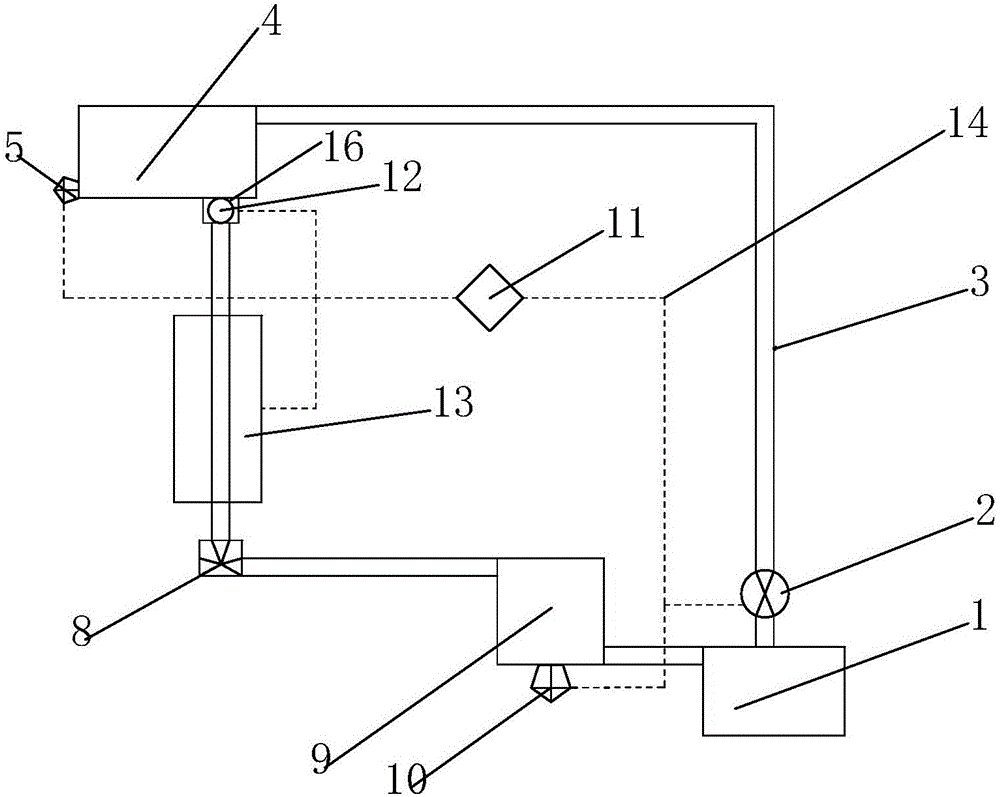
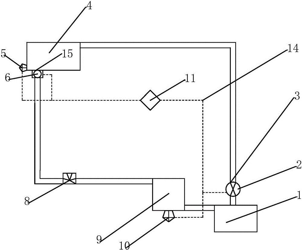
[0027] Such as figure 1 As shown, a circulation device of an electric vehicle battery thermal management system according to the present invention includes a main water tank 1, a motor water pump 2, a pipeline 3, an auxiliary water tank 4, a water level sensor 5, a solenoid valve 6, and a pipeline heater 7 , three-way valve 8, lithium battery pack 9, temperature sensor 10, controller 11, solenoid valve two 12, cooling box 13, motor water pump 2, temperature sensor 10, controller 11, water level sensor 5, solenoid valve one 6 and electromagnetic The valve 2 12 is correspondingly connected through the wire 14 to form a battery thermal management control system. The main water tank 1, the auxiliary water tank 4, the solenoid valve 2 12, the cooling tank 13, the three-way valve 8 and the lithium battery pack 9 are connected through the pi...


PUM


Abstract

The invention relates to the technical field of electric vehicles, in particular to a circulating device of an electric vehicle battery thermal management system and a control method of the circulating device. The circulating device comprises a main water tank, a motor water pump, an auxiliary water tank, a water level sensor, a solenoid valve I, a pipeline heater, a three-way valve, a lithium battery pack, a temperature sensor, a controller, a solenoid valve II and a heat dissipation tank, wherein the motor water pump, the temperature sensor, the controller, the water level sensor, the solenoid valve I and the solenoid valve II are connected with one another via conducting wires to form a control system; the main water tank, the auxiliary water tank, the solenoid valve I, the solenoid valve II, the heat dissipation tank, the three-way valve and the lithium battery pack are connected with one another via pipelines to form a heat dissipation loop; the main water tank, the auxiliary water tank, the solenoid valve I, the pipeline heater, the three-way valve and the lithium battery pack are connected with one another via pipelines to form a heating loop. Through the three different circulating modes, a battery can work in a stable, efficient and safe temperature range, so that the excessive heat loss is greatly reduced to achieve the purpose of saving energy, and the service life of the battery is prolonged.

Description

technical field [0001] The invention relates to the technical field of electric vehicles, in particular to a circulation device and a control method of a battery thermal management system of an electric vehicle. Background technique [0002] 2016 is the first year of my country's "Thirteenth Five-Year Plan". In terms of electric vehicles, the Ministry of Science and Technology has researched and formulated a special plan for the development of electric vehicle technology during the "Twelfth Five-Year Plan". Performance and other characteristics are taken as the key breakthroughs. The technical performance breakthrough of power batteries is restricted by many external conditions, especially the temperature conditions. A good operating temperature is the prerequisite for safe and efficient work of power batteries. Therefore, it is of great significance to develop an effective battery thermal management system and design a stable and efficient battery box, heat dissipation and h...

Claims


Application Information

Patent Timeline
Patent Type & Authority Applications(China)
IPC IPC(8): H01M10/613H01M10/615H01M10/635H01M10/6568H01M10/6571H01M10/625
CPCH01M10/613H01M10/615H01M10/625H01M10/635H01M10/6568H01M10/6571Y02E60/10
Inventor 刘志恩严鹏郑安棋路程肖广聪田野陈雨青曾雄何颖
Owner WUHAN UNIV OF TECH
Why Eureka
Try Eureka