Video signal monitoring method and video signal monitoring system

A video signal and target video technology, applied in the field of signal processing, can solve the problems of reducing user experience, unable to guarantee the reliability of detection results and monitoring efficiency, etc.

Active Publication Date: 2016-10-12
北京华兴宏视技术发展有限公司
View PDF5 Cites 15 Cited by
  • Summary
  • Abstract
  • Description
  • Claims
  • Application Information

AI Technical Summary

Problems solved by technology

TV programs transmitted on the telecommunication network and the Internet are also faced with broadcast security issues. Even compared with traditional broadcast TV networks, the situation of TV programs in new media services is more complicated: first, image quality, coding standards, Diversity in encapsulation formats, etc.; secondly, the diversity of transmission channels; and thirdly, the diversity of receiving terminals, which makes the technical requirements for content security monitoring higher.
[0004] During the entire transmission process of multimedia information (video and audio signals), some video and audio content is changed (that is, the signal is abnormal), but the transmission process itself can operate normally. From the perspective of the broadcaster, there is a broadcast fault, and the severity of the fault depends on the tampered content; from the user's point of view, the user experience will be reduced to varying degrees
In the related technology, most of the broadcasting channel classification control system of the TV station adopts the original end and signal manual monitoring method, through the real-time observation of human eyes to find faults and carry out alarm processing, but the manual detection method cannot guarantee the reliability of the detection results and monitoring efficiency

Method used


Image

  • Video signal monitoring method and video signal monitoring system
  • Video signal monitoring method and video signal monitoring system
  • Video signal monitoring method and video signal monitoring system

Examples


Embodiment Construction

[0078] In order to understand the above-mentioned purpose, features and advantages of the present invention more clearly, the present invention will be further described in detail below in conjunction with the accompanying drawings and specific embodiments. It should be noted that, in the case of no conflict, the embodiments of the present application and the features in the embodiments can be combined with each other.

[0079] In the following description, many specific details are set forth in order to fully understand the present invention. However, the present invention can also be implemented in other ways different from those described here. Therefore, the protection scope of the present invention is not limited by the specific details disclosed below. EXAMPLE LIMITATIONS.

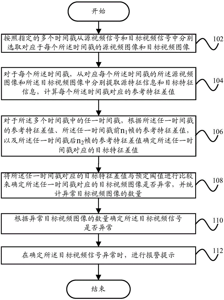
[0080] figure 1 A schematic flowchart of a video signal monitoring method according to an embodiment of the present invention is shown.

[0081] Such as figure 1 As shown, the video signal monitor...


PUM


Abstract

The invention provides a video signal monitoring method and a video signal monitoring system. The video signal monitoring method comprises the steps of respectively selecting a source video image and a target video image corresponding to each timestamp from a source video signal and a target video signal according to a plurality of appointed timestamps; respectively extracting source feature information and target feature information from the source video image and the target video image corresponding to each timestamp, and computing a reference feature difference value corresponding to each timestamp; according to the reference feature difference value of any timestamp, the reference feature difference value of previous n1 frames of any timestamp and the reference feature difference value of latter n2 frames of any timestamp, determining a target feature difference value corresponding to the any timestamp; comparing the target feature difference value corresponding to the any timestamp with a predetermined threshold to determine whether the target video image corresponding to the any timestamp is abnormal, and counting the quantity of the abnormal target video images; and giving an alarm for prompting when determining that the target video signal is abnormal according to the quantity of the abnormal target video images.

Description

technical field [0001] The invention relates to the technical field of signal processing, in particular to a video signal monitoring method and a video signal monitoring system. Background technique [0002] In the field of traditional radio and television, in order to ensure the safe, reliable and high-quality operation of the cable digital TV system, it is necessary to deploy a multi-level monitoring and monitoring system to monitor the quality and content of the signals at the front end of the broadcast digital TV programs. Management, to achieve monitoring data scheduling, monitoring screen scheduling, equipment management and broadcast program content management, thereby improving the efficiency of cable digital TV network operation and maintenance, saving network operation and maintenance costs and human resources. [0003] Content security monitoring, as a means of monitoring the security of TV program broadcasting, is a major issue related to national cultural securi...

Claims


Application Information

Patent Timeline
Patent Type & Authority Applications(China)
IPC IPC(8): H04N21/442H04N21/234H04N21/44H04N17/00
CPCH04N17/00H04N21/23418H04N21/44008H04N21/442
Inventor 高永英彭兴涛武宇文
Owner 北京华兴宏视技术发展有限公司
Why Eureka
Try Eureka