Parts-placing apparatus

A technology for installing devices and installation positions, applied in the direction of electrical components, electrical components, etc., can solve the problems of inaccuracy, etc., and achieve the effect of proper detection and stable installation

Active Publication Date: 2016-10-12
FUJI KK
View PDF4 Cites 11 Cited by
  • Summary
  • Abstract
  • Description
  • Claims
  • Application Information

AI Technical Summary

Problems solved by technology

For example, the component mounting device of Patent Document 1 captures a side image of the suction nozzle from the side immediately before mounting, calculates the distance from the front end of the suction nozzle to the lower end of the suctioned component bas

Method used


Image

  • Parts-placing apparatus
  • Parts-placing apparatus
  • Parts-placing apparatus

Examples


Embodiment Construction

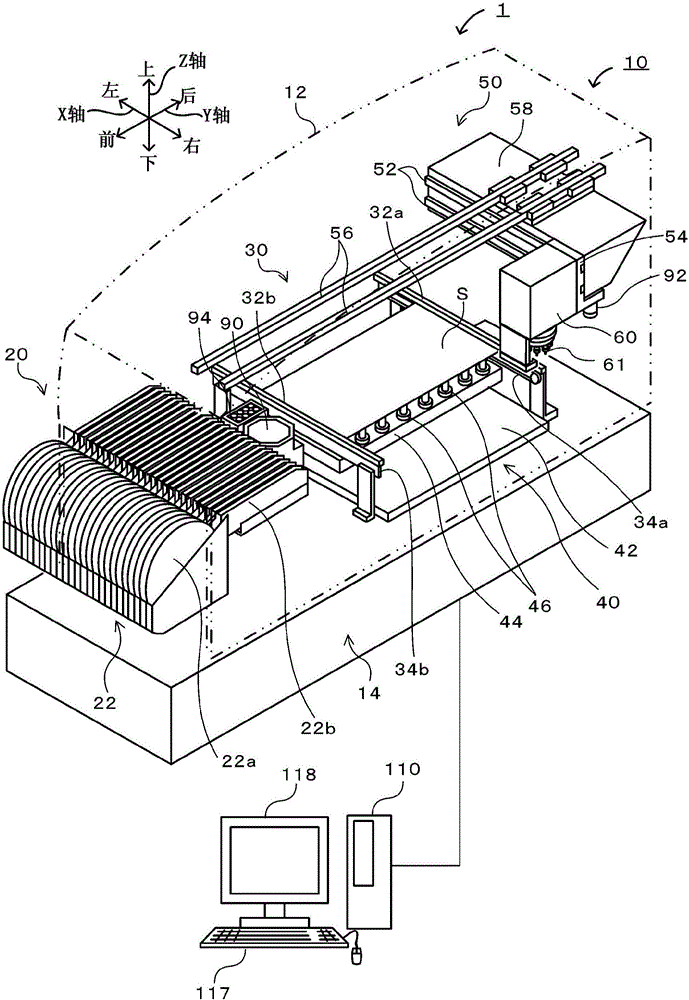
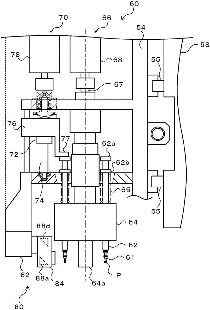
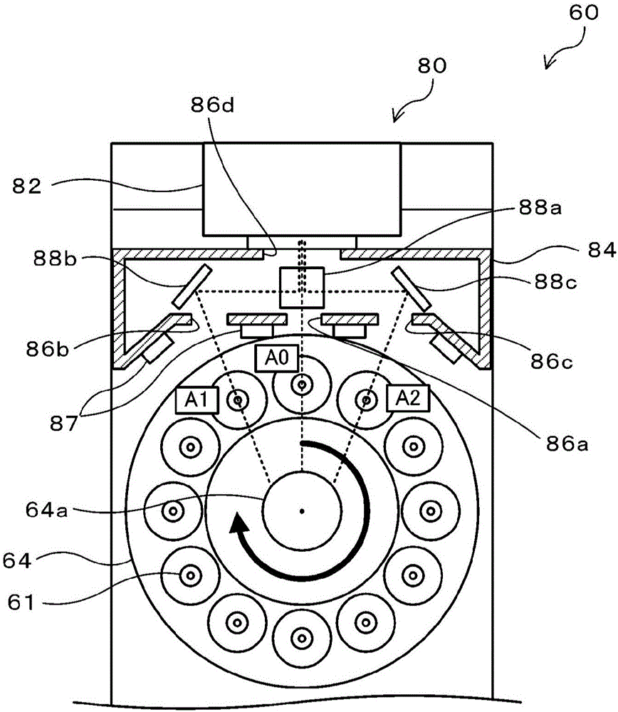
[0028] Next, embodiments of the present invention will be described using the drawings. figure 1 It is a configuration diagram showing a schematic configuration of the component mounting system 1 . figure 2 is a schematic configuration diagram showing a side configuration of the head unit 60, image 3 is a schematic structural diagram showing the structure of the lower surface of the head unit 60, Figure 4 It is a block diagram showing the electrical connection relationship between the control device 100 and the management device 110 . The component mounting system 1 includes: a component mounting device 10 that mounts (mounts) an electronic component (hereinafter referred to as "component") P on a circuit board (hereinafter referred to as "substrate") S; and manages and manages the entire system. device 110. Also, in this embodiment, figure 1 The left and right direction is the X axis direction, the front and rear direction is the Y axis direction, and the up and down d...


PUM


Abstract

A parts-placing apparatus is provided with a rotary head, the rotary head having multiple adsorption nozzles attached thereto. On the basis of a post-adsorption image (S130) and a pre-placing image (S180), the adsorption deviation (position change) of parts from after the adsorption of the parts to before the placing of the parts is determined (S190). The post-adsorption image is obtained by capturing an image of the side of the adsorption nozzle immediately after the adsorption of the parts and the pre-placing image is obtained by capturing an image of the side of the adsorption nozzle immediately before the placing of the parts. Therefore, it is possible to appropriately detect the generation of the adsorption deviation in the parts that are adsorbed by using the adsorption nozzles on the basis of the movement or the like of the adsorption nozzles caused by the rotation of the rotary head.

Description

technical field [0001] The present invention relates to component mounting devices. Background technique [0002] Conventionally, in a component mounting apparatus for mounting a suction component sucked by a suction nozzle on a board, a configuration is known in which the presence or absence of suction failure of the suction component is determined so that the suction component can be accurately mounted on the board. For example, the component mounting device of Patent Document 1 captures a side image of the suction nozzle from the side immediately before mounting, calculates the distance from the front end of the suction nozzle to the lower end of the suctioned component based on the side image, and compares the calculated distance with the Compared with the reference value, it is judged whether there is a so-called upright adsorption that cannot accurately adsorb the upper surface of the element and the adsorption element is tilted. [0003] Patent Document 1: Japanese P...

Claims


Application Information

Patent Timeline
IPC IPC(8): H05K13/04H05K13/08
CPCH05K13/041H05K13/0812H05K13/0813H05K13/0408
Inventor 川合英俊
Owner FUJI KK
Why Eureka
Try Eureka