A rotary cultivator with an automatic following clutch device

A clutch device and automatic follow-up technology, applied in the field of rotary tillers, can solve the problems of greatly increased rotational resistance of rotary tillers, overload damage of tools, and decreased rotary tillage efficiency, and achieves the effect of solving insufficient torque

Active Publication Date: 2020-01-14
湖南湘源金穗智能装备有限公司
View PDF6 Cites 0 Cited by
  • Summary
  • Abstract
  • Description
  • Claims
  • Application Information

AI Technical Summary

Problems solved by technology

However, in this technical solution, the lifting action of the rotary tiller is basically synchronous with the clutch state of the belt clutch wheel, which will bring two disadvantages: one is that the maximum torque output by the belt clutch wheel to the rotary tiller is only when the rotary tiller is in the The normal working position can only be realized. If the working position of the rotary tiller is raised for shallow tillage, the belt clutch wheel will automatically exit the fully engaged state and enter the semi-engaged state, unable to output the maximum torque, resulting in a serious decline in the efficiency of rotary tillage; the second is rotary tillage When the machine is lowered from a high position and enters the operation process, it is easy to see that the rotary tiller has been lowered into the soil but has not yet entered the normal rotation state. Partial silting of the soil will greatly increase the rotation resistance of the rotary tiller, which will cause overload damage to the machine tool.

Method used


Image

  • A rotary cultivator with an automatic following clutch device

Examples


Embodiment Construction

[0009] Below, the specific implementation manners of the present invention will be further described in conjunction with the accompanying drawings.

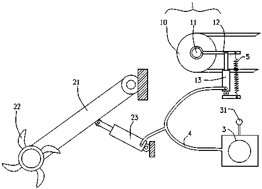
[0010] figure 1 It shows an embodiment of a rotary cultivator with an automatic following clutch device, including a belt clutch wheel 1 driven by power. The belt clutch wheel 1 includes a pulley 10, an output shaft 11, and a separation pawl 12. The output shaft 11 drives the rotary cultivator. , the rotary tiller includes a transmission box 21 that is hinged at one end on the frame, and the rotary tiller 22 is installed at the other end of the transmission box 21; the hydraulic cylinder one 23 is connected to the transmission box 21, and can push the transmission box 21 around the hinge Point rotation to lift the working position of the rotary tiller 22, the hydraulic cylinder two 13 is connected to the separation claw 12 of the belt clutch wheel 1, and the separation claw 12 can be promoted to rotate to disconnect the transmiss...


PUM


Abstract

The invention provides a rotary cultivator with an automatic following clutch device. The rotary cultivator comprises a power-driven belt clutch wheel which comprises a belt wheel, an output shaft and a disengaging pawl; the output shaft drives a rotary cultivation device; the rotary cultivation device comprises a transmission case with one end movably hinged to a rack and a rotary cultivation cutter is installed on the other end of the transmission case; a first hydraulic oil cylinder is connected with the case body of the transmission case and a second hydraulic oil cylinder is connected with the disengaging pawl of the belt clutch wheel; oil paths of the first hydraulic oil cylinder and the second hydraulic oil cylinder communicate with each other and are driven by a hydraulic pump; a controller controls the hydraulic pump to convey oil to the oil paths or unload oil from the oil paths; the disengaging pawl is provided with a resetting spring; spring force makes the disengaging pawl return to the resetting position and the minimum resetting moment applied to the disengaging pawl by the resetting spring is greater than or equal to the thrust moment applied to the disengaging pawl by the second hydraulic oil cylinder when the rotary cultivation cutter just rises to the highest position. The problems that the torque of a rotary cultivation cutter in a shallow ploughing state is insufficient and a rotary cultivation cutter is damaged because of overload when being lowered into mud.

Description

technical field [0001] The invention relates to an agricultural cultivating implement with a driven rotary working part, in particular to a rotary cultivator with an automatic following clutch device. Background technique [0002] For the known rotary cultivator, automatically associating the opening and closing action of the clutch device with the lifting action of the rotary tiller has important practical significance for simplifying the operation and improving the farming efficiency. For example, the patent document whose publication number is CN102823352A discloses a rotary tiller with an automatic clutch device, including a liftable rotary tiller connected to the frame, and the rotary tiller includes a transmission box and a rotary tiller installed on the output shaft of the transmission box. For the tiller, the transmission box body is articulated on the frame with the transmission box input shaft as the axis, and the lifting mechanism is connected to the transmission ...

Claims


Application Information

Patent Timeline
Patent Type & Authority Patents(China)
IPC IPC(8): A01B33/08
Inventor 李源湘胡华锋
Owner 湖南湘源金穗智能装备有限公司
Why Eureka
Try Eureka