Sand-iron separation device

A separation device, technology of sand and iron, applied in the direction of casting molding equipment, cleaning/processing machinery of casting mold materials, metal processing equipment, etc., can solve the problems of no recycling method, waste, inapplicability, etc., and achieve the effect of simple structure

Inactive Publication Date: 2016-10-19
CHONGQING DONGHONGXIN TECH
View PDF0 Cites 3 Cited by
  • Summary
  • Abstract
  • Description
  • Claims
  • Application Information

AI Technical Summary

Problems solved by technology

A large amount of waste sand will be produced in foundry production, and waste sand contains a certain amount of iron, and direct discharge will cause great waste. At present, there is no suitable recycling method, and there is no special sorting equipment for foundry sand. Ordinary beneficiation magnetic separators and air separators are very inefficient for the separation of foundry sand, which is very inapplicable, and the separation cost is high

Method used


Image

  • Sand-iron separation device

Examples


Embodiment Construction

[0009] Below in conjunction with accompanying drawing and embodiment the present invention will be further described:

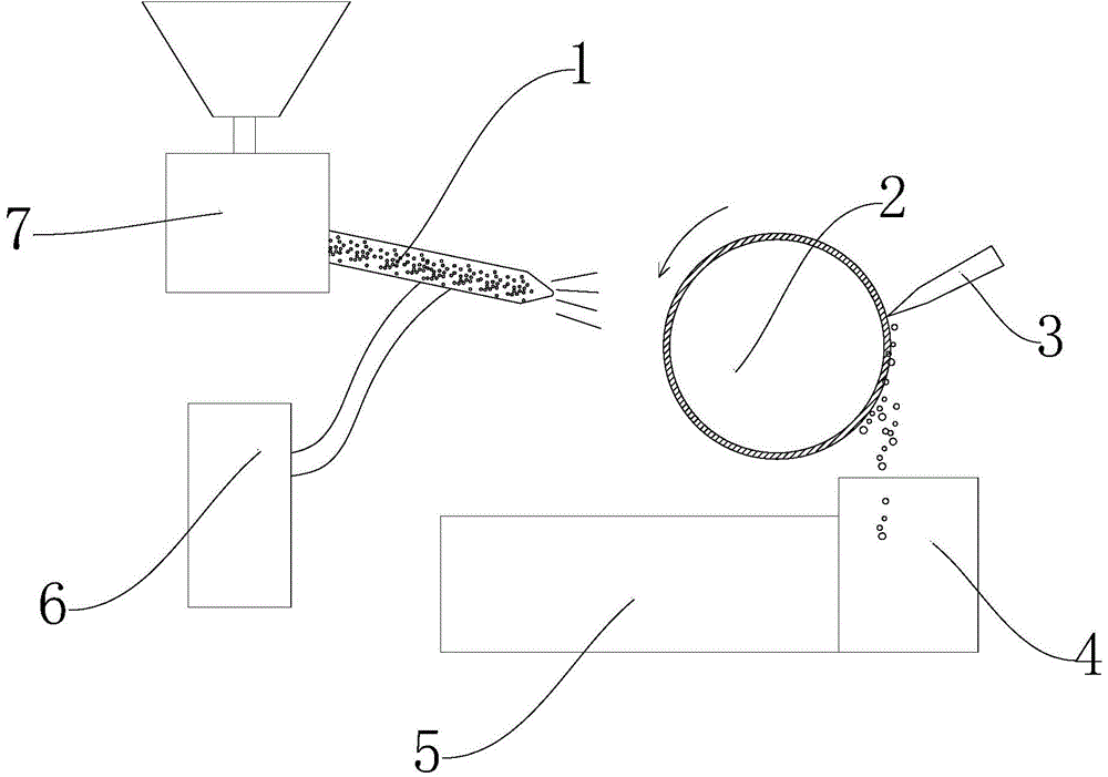
[0010] see figure 1 A sand and iron separation device, comprising a discharge device and a circular roller 2, the discharge device includes a feed cylinder 7 and an air compressor 6, the feed cylinder 7 is connected to the spray gun 1, and the air compressor 6 Connected with the spray gun 1, the outer surface of the circular roller 2 is covered with a magnet layer, the discharge device is located at the upper left of the circular roller 2, and its outlet is inclined to the direction of the circular roller 2, the circular roller A sand storage device 5 is arranged below the roller 2 , a scraper blade 3 is arranged on the upper right of the circular roller 2 , and an iron storage device 4 is arranged below the scraper blade 3 .

[0011] When the present invention is in use, the casting sand is first put into the feeding cylinder 7, the air compressor 6 is star...


PUM


Abstract

The invention discloses a sand-iron separation device. The sand-iron separation device comprises a discharging device and a round roller, wherein the discharging device comprises a feeding cylinder and an air compressor, the feeding cylinder is connected with a spray gun, the air compressor is connected with the spray gun, and the round roller is coated with a magnet layer; the discharging device is located above the left side of the round roller, and an outlet of the discharging device inclines towards the round roller; a sand storage device is arranged below the round roller, a scraper blade is arranged above the right side of the round roller, and an iron storage device is arranged below the scraper blade. The sand-iron separation device is simple in structure, and iron and sand can be separated out quickly.

Description

technical field [0001] The invention relates to a sand and iron separation device. Background technique [0002] Foundry sand is a granular refractory material used to configure molding sand and core sand in foundry production. A large amount of waste sand will be produced in foundry production, and waste sand contains a certain amount of iron, and direct discharge will cause great waste. At present, there is no suitable recycling method, and there is no special sorting equipment for foundry sand. Ordinary beneficiation magnetic separators and air separators are very inefficient for the separation of foundry sand, which is very inapplicable, and the separation cost is high. Contents of the invention [0003] In view of the above-mentioned defects in the prior art, the technical problem to be solved by the present invention is to provide a separation device for sand and iron, which has a simple structure and can separate sand and iron relatively quickly. [0004] To achie...

Claims


Application Information

Patent Timeline
Patent Type & Authority Applications(China)
IPC IPC(8): B22C5/06
Inventor 彭君秀
Owner CHONGQING DONGHONGXIN TECH
Why Eureka
Try Eureka