Surgical instrument and surgical robot adopting same
A technique for surgical instruments and guiding mechanisms, applied in the field of medical instruments, can solve the problems of difficult parts processing, poor operation accuracy, complex structure, etc., and achieve the effects of low processing cost, easy assembly, and simple structural relationship.
- Summary
- Abstract
- Description
- Claims
- Application Information
AI Technical Summary
Problems solved by technology
Method used
Image

Examples
Embodiment 1
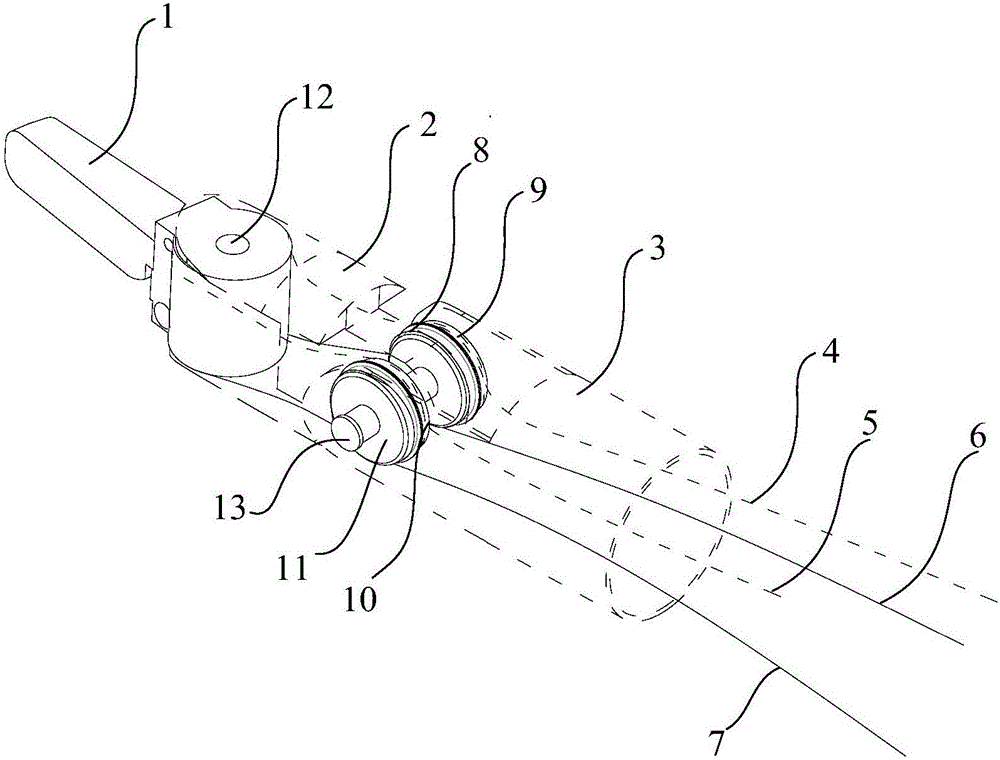
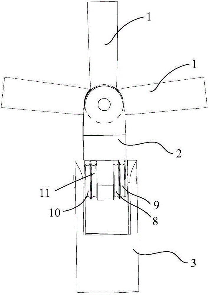
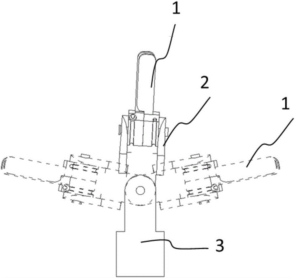
[0046] Embodiment 1 provides a surgical instrument capable of moving with multiple degrees of freedom, such as figure 1 As shown, it is a schematic structural diagram of the surgical instrument according to Embodiment 1 of the present invention. In order to show the structure of the surgical instrument more clearly, some elements are shown in dotted lines.
[0047] The surgical instrument includes a front end 1, a wrist 2, a base 3, a guide mechanism and a traction unit; the front end 1 is rotatably connected to the wrist 2 and forms a first axis of rotation, and the wrist 2 is rotatably connected to the base 3 and forms a second axis of rotation. Two rotation axes, the first rotation axis and the second rotation axis are non-coplanar and perpendicular.
[0048] The traction unit includes four traction bodies, which are respectively the first traction body 4, the second traction body 5, the third traction body 6 and the fourth traction body 7; the first traction body 4 and the...
Embodiment 2
[0066] The difference from Embodiment 1 is that the front end 1 of this embodiment is a part structure for realizing deflection and opening and closing movement, specifically as Image 6 as shown, Image 6 It is a structural schematic diagram of the surgical instrument of the second embodiment of the present invention.
[0067] The front end 1 includes a relatively movable first clamping portion 111 and a second clamping portion 112, the first clamping portion 111 includes a relative first front end and a first rear end; the second clamping portion 112 includes an opposite second clamping portion 112. The front end and the second rear end, the first front end and the second front end cooperate to clamp objects; the first rear end and the second rear end respectively rotate and connect the wrist 2 and share the first rotation axis .
[0068] Both the first traction body 4 and the second traction body 5 are connected to the second rear end of the second clamping portion 112 . ...
Embodiment 3
[0077] The difference between the present embodiment and the second embodiment lies in that besides the above-mentioned four main guide wheels, the guide mechanism has additionally added four guide guide wheels. For details, please refer to Figure 8 , Figure 8 It is a structural schematic diagram of the surgical instrument of the third embodiment of the present invention. However, it should be noted that the guiding mechanism of this embodiment and the connection manner between the guiding mechanism and the traction body are also applicable to the first embodiment.
[0078] Specifically, in addition to the first main guide wheel 8, the second main guide wheel 9, the third main guide wheel 10, and the fourth main guide wheel 11, the guiding mechanism of this embodiment also includes four guiding guide wheels, which are respectively the first One guidance to the wheel 14, the second guidance to the wheel 15, the third guidance to the wheel 16 and the fourth guidance to the wh...
PUM
| Property | Measurement | Unit |
|---|---|---|
| Rotation angle | aaaaa | aaaaa |
Abstract
Description
Claims
Application Information
 - R&D
- Intellectual Property
- Life Sciences
- Materials
- Tech Scout
- Unparalleled Data Quality
- Higher Quality Content
- 60% Fewer Hallucinations
Browse by: Latest US Patents, China's latest patents, Technical Efficacy Thesaurus, Application Domain, Technology Topic, Popular Technical Reports.
© 2025 PatSnap. All rights reserved.Legal|Privacy policy|Modern Slavery Act Transparency Statement|Sitemap|About US| Contact US: help@patsnap.com