Intelligent mattress

A mattress, intelligent technology, applied in the mattress field, can solve the problems of high driver requirements, large load force, and difficulty in reducing costs, and achieve the effects of reduced requirements, long service life, and reduced cost and failure rate.

Active Publication Date: 2016-10-26
NINGBO KANGMAILONG MEDICAL APP
View PDF7 Cites 9 Cited by
  • Summary
  • Abstract
  • Description
  • Claims
  • Application Information

AI Technical Summary

Problems solved by technology

[0003] Nursing beds currently available on the market have a back panel, a waist panel and a seat panel that are hinged from front to back in sequence. Sleep comfort and convenience for special users such as the bedridden elderly to eat and move their bodies. However, the drives of these nursing beds bear a large load, so the requirements for the drives are very high, making it difficult to reduce the cost

Method used


Image

  • Intelligent mattress
  • Intelligent mattress
  • Intelligent mattress

Examples


Embodiment 1

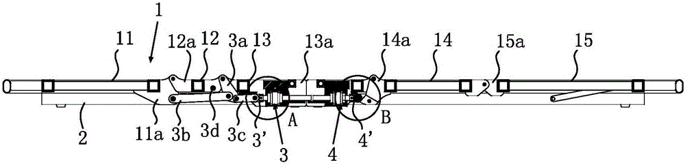
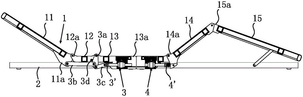
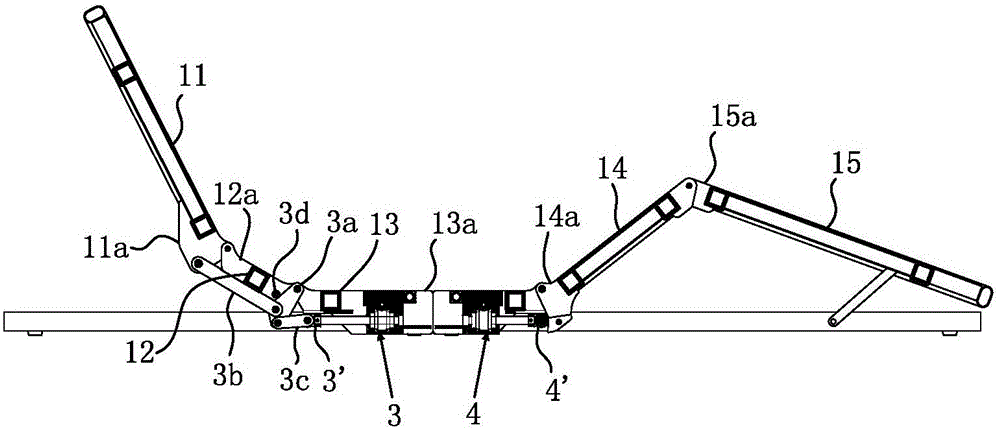
[0043] Such as figure 1 As shown, the present invention provides a smart mattress, including a bed body 1 and a bed frame 2 for supporting the bed body 1. The bed body 1 includes a back frame 11, a waist frame 12, and a seat frame 13 hinged from front to back in sequence. , thigh frame 14 and calf frame 15, back frame 11, waist frame 12, seat frame 13, thigh frame 14 and calf frame 15 tops are respectively installed with bed boards or covered with soft materials. When users use it, they can also add The mat or quilt improves the comfort of use. The seat frame 13 is fixed on the bed frame 2. The bed frame 2 is provided with a first driver 3 with a driving end 3' and a second driver 4 with a driving end 4'. The bed frame 2 is hinged with a first connecting rod 3a, and a second connecting rod 3b is provided between the first connecting rod 3a and the back frame 11. The driving end 3' of the first driver 3 performs telescopic movement to drive the first connecting rod 3a to swing,...

Embodiment 2

[0056] Such as Figure 7 to Figure 11 and Figure 7a As shown, the difference between this embodiment and Embodiment 1 is that there is no need to set a third connecting rod, the first connecting rod 3a has a first force-receiving part 3a', and the first force-receiving part 3a' is the first connecting rod 3a, the first force-receiving part 3a' is located on the telescopic movement path of the driving end 3' of the first driver 3, and when the driving end 3' of the first driver 3 moves telescopically, the force acts directly on the first force-receiving part 3a' Drive the first connecting rod 3a to swing.

[0057] In this embodiment, the gear box 323 of the first driver 3 and the gear box 423 of the second driver 4 are integrally formed and fixed on the seat plate 13a, the integrally formed gear box is disconnected from the thigh frame 14 together with the seat frame 13, The Smart Mattress can also be quickly disassembled into two parts.

[0058] It should be noted that the...

Embodiment 3

[0060] Such as Figure 12 and Figure 12a As shown, the difference between this embodiment and the above embodiment is that the second connecting rod 3b is provided with a strip-shaped guide hole 3b', and the bed frame 2 is provided with a guide post 22 extending into the guide hole 3b' and a support The guide plate 23 is arranged below the second connecting rod 3b and parallel to the guide hole. The second connecting rod 3b can slide along the length direction of the guide hole and the guide plate. 11a', one end of the second link 3b is located on the swing path of the first link 3a, and the back frame force receiving part 11a' is located on the sliding path of the other end of the second link 3a.


PUM


Abstract

The invention, which belongs to the technical field of the mattress, discloses an intelligent mattress comprising a bed body and a bed frame for supporting the bed body. The bed body consists of a back frame, a waist frame, and a seat frame, wherein the frames are in a hinge joint successively. The seat frame is fixed on the bed frame. A first driver with a driving end is arranged at the bed frame; a first connecting rod is in hinge joint with the bed frame; and a second connecting rod is arranged between the first connecting rod and the back frame. The driving end of the first driver makes stretching movement to drive the first connecting rod to swing. One end of the second connecting rod is linked to the first connecting rod and the other end can apply a force to the back frame to enable the back frame to overturn up and down relative to the waist frame. A pin shaft arranged in a swinging region of the first connecting rod is arranged at the waist frame; and the first connecting rod can apply a force to the waist frame by the pins shaft, so that the waist frame can overturn up and down relative to the seat frame. The intelligent mattress has the advantage: the loading force applied on the driver can be reduced.

Description

technical field [0001] The invention relates to mattresses, in particular to an intelligent mattress. Background technique [0002] Calculated based on normal work and rest, people need about one-third of sleep time every day, and the comfort of the bed determines the quality of sleep to a large extent. Especially for bedridden old people, disabled people or patients, if they lie flat or on their sides for a long time, local pressure will be caused, resulting in many health problems. [0003] Nursing beds currently available on the market have a back panel, a waist panel and a seat panel that are hinged from front to back in sequence. Sleep comfort and convenience for special users such as the bedridden elderly to eat and move their bodies. However, the drives of these nursing beds bear a large load, so the requirements for the drives are very high, making it difficult to reduce the cost. Contents of the invention [0004] The purpose of the present invention is to provi...

Claims


Application Information

Patent Timeline
Patent Type & Authority Applications(China)
IPC IPC(8): A61G7/015
CPCA61G7/015A61G7/018A61G2200/32
Inventor 李路平覃鸿陆柯军黄春峰
Owner NINGBO KANGMAILONG MEDICAL APP
Why Eureka
Try Eureka