
Elevator braking device and method

An elevator braking and motion technology, applied in the direction of the hoisting device, etc., can solve the problems of casualties, open the door and walk up the stairs, and reduce the contact surface, and achieve the effect of reducing casualties, avoiding safety failures, and occupying a small space.

Active Publication Date: 2018-11-06
SUZHOU BALANCE ELEVATOR TECH CO LTD
View PDF9 Cites 0 Cited by
  • Summary
  • Abstract
  • Description
  • Claims
  • Application Information

AI Technical Summary

Problems solved by technology

[0003] 1. When the elevator stops at the floor, after the hall door and the car door are opened, passengers and goods enter and exit the car. At this time, it cannot be ruled out that the overload and vibration cause insufficient braking force of the working brake, and there is oil on the braking surface, and the mechanical parts of the brake fail. Such as brake pad wear, energy storage compression spring aging and plastic deformation, etc.;
[0004] 2. Although the brake has sufficient braking force, there will still be overload and vibration, which will cause the steel wire rope to slip on the traction wheel due to insufficient traction (there is oil on the contact surface between the steel wire rope and the traction wheel, and the steel wire rope will become thinner after long-term use. The contact surface with the traction wheel groove is reduced, the working surface of the traction wheel is worn, the replacement of unqualified traction wheels, etc.); and once the braking force or traction force is insufficient, it will cause serious accidents of casualties;
[0005] 3. The control unit of the frequency converter is faulty, and the wrong command is issued, causing an accident of opening the door and walking the ladder

Method used


Image

  • Elevator braking device and method
  • Elevator braking device and method
  • Elevator braking device and method

Examples


Embodiment

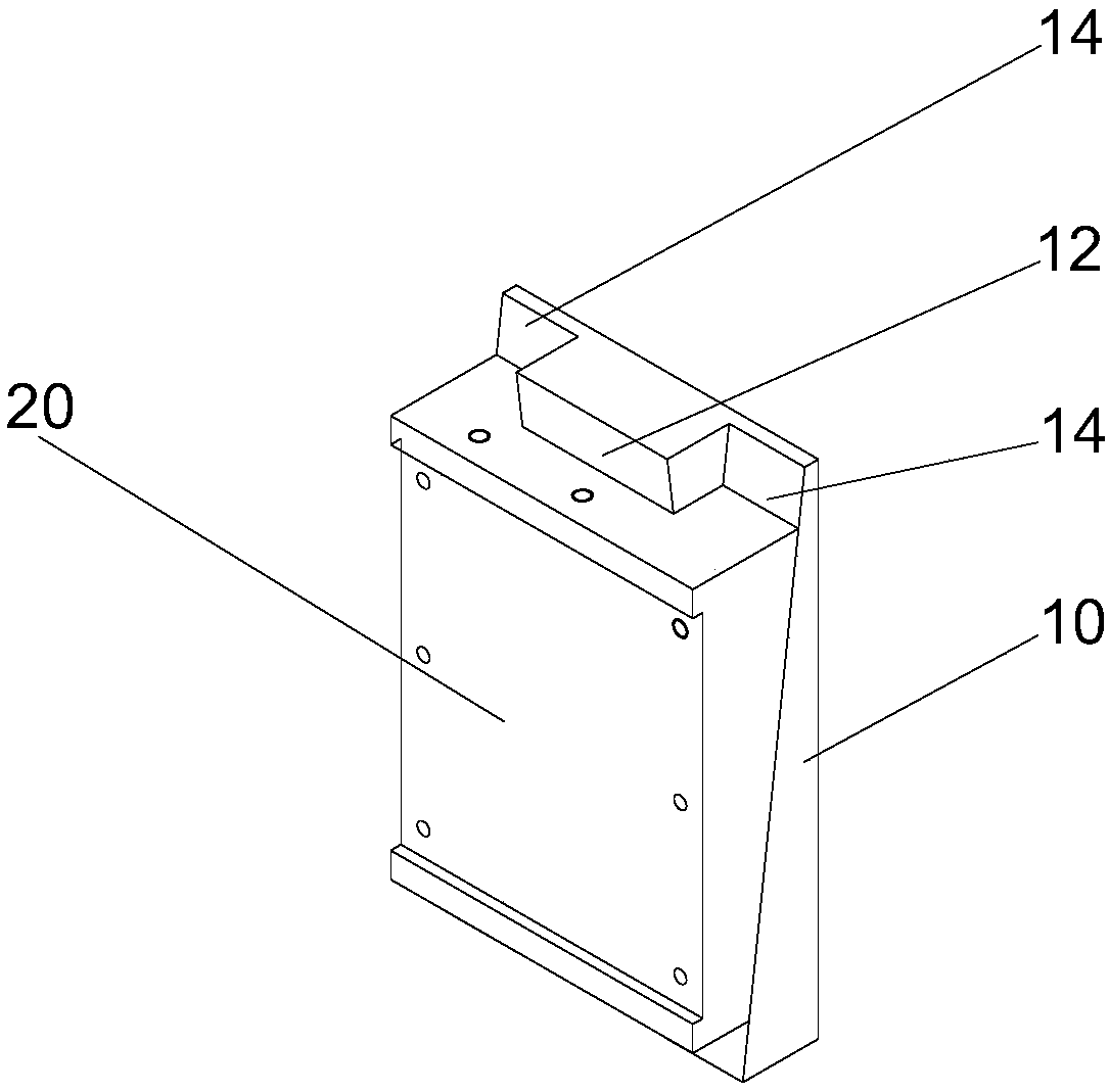
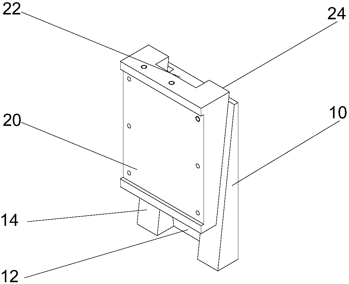
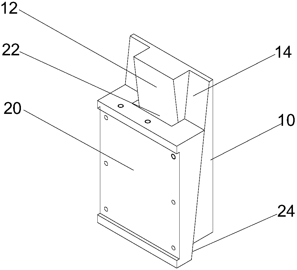
[0037] Example: such as Figure 1-8 As shown, the present invention provides a first embodiment of an elevator braking device, which is used for two-way braking of a steel wire rope 42 or a guide rail, comprising: at least one pair of fixed clips 10 that can reciprocate relative to the fixed clips 10 and At least one pair of movable clamping blocks 20 located on both sides of the steel wire rope 42 or the guide rail, the driving mechanism 30 for driving the movable clamping block 20 to move, and the friction plate 50 arranged on the movable clamping block 20 and in frictional contact with the steel wire rope 42 or the guide rail, wherein the fixed The clamping block 10 is provided with a first slope 12 on one side and a pair of second slopes 14 located on both sides of the first slope 12, and the movable clamping block 20 is provided with a third slope 22 cooperating with the first slope 12 on one side, And a pair of fourth slopes 24 correspondingly matched with the correspond...


PUM


Abstract

The invention discloses an elevator braking device and an elevator braking method. The elevator braking device carries out two-way braking on a steel wire rope or a guide rail. The elevator braking device comprises at least one pair of fixed clamping blocks, at least one pair of movable clamping blocks, a driving mechanism and friction plates, wherein the movable clamping blocks can make reciprocating motion relative to the fixed clamping blocks and are positioned at the two sides of the steel wire rope; the driving mechanism drives the movable clamping blocks to move; the friction plates are arranged on the corresponding movable clamping blocks and are in frictional contact with the steel wire rope; and the fixed clamping blocks and the movable clamping blocks are mutually matched in a wedge-shaped block manner. Through the matching of the front and back wedge-shaped faces of the fixed clamping blocks and the movable clamping blocks, two-way braking on the steel wire rope and the self-locking effect are realized, so that the braking purpose is reached, safety failure is avoided, and serious accidents resulting in casualties are reduced. The elevator braking device is simple in structure, convenient to mount, and small in floor area, and can be mounted in an elevator machine room or beside a traction machine; old elevator transformation is facilitated; and the problem that the conventional elevator has no safety brake mounting position is solved.

Description

technical field [0001] The invention relates to an elevator braking device and method. Background technique [0002] With the development of urban construction and the improvement of people's quality of life, when residents can enjoy good land public transportation services when traveling, they also desire to obtain convenient vertical transportation in their residences. Therefore, in recent years, the number of elevators has grown rapidly, and the number of elevators in the country has increased from 285,000 in 2003 to 3,009,300 in 2013. As a special means of transportation, the elevator is an indispensable means of transportation for ordinary people. It brings unprecedented convenience to people's daily life. The safety and reliability of its operation are issues that many people are generally concerned about. The quality of residential elevators is good. It directly affects the quality of life of ordinary people. In 2014, the General Administration of Quality Supervision...

Claims


Application Information

Patent Timeline
Patent Type & Authority Patents(China)
IPC IPC(8): B66D5/02B66D5/24
CPCB66D5/02B66D5/24
Inventor 李军
Owner SUZHOU BALANCE ELEVATOR TECH CO LTD
Learn More