Retaining wall structure for sponge city construction

A sponge city and retaining wall technology, applied in applications, construction, sea area engineering, etc., can solve the problems of not being able to make full use of the ecological purification function of the soil on both sides of the strait, and achieve the effect of reducing waterlogging disasters

Active Publication Date: 2016-10-26
POWERCHINA CHENGDU ENG
View PDF8 Cites 7 Cited by
  • Summary
  • Abstract
  • Description
  • Claims
  • Application Information

AI Technical Summary

Problems solved by technology

This method can make the precipitation infiltrate and discharge into the river through the bank slope soil, but the water flow in th

Method used


Image

  • Retaining wall structure for sponge city construction
  • Retaining wall structure for sponge city construction
  • Retaining wall structure for sponge city construction

Examples


Embodiment Construction

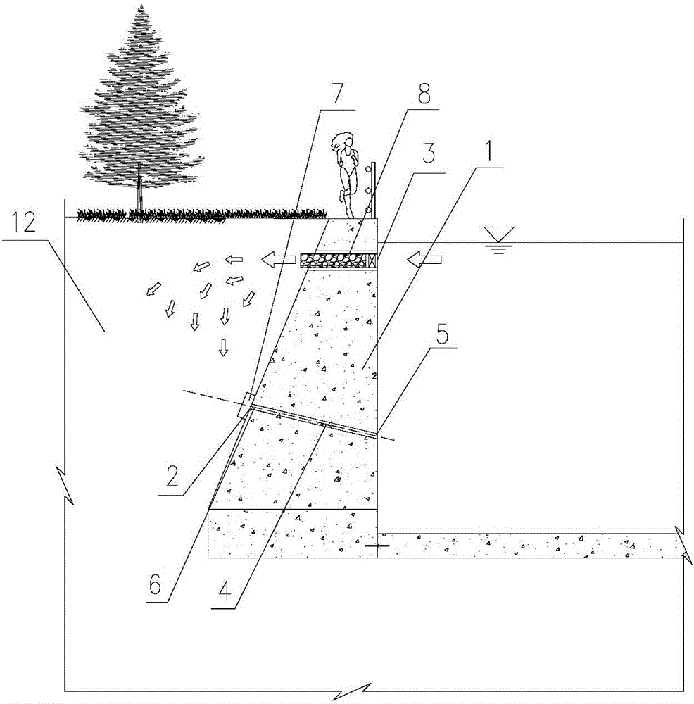
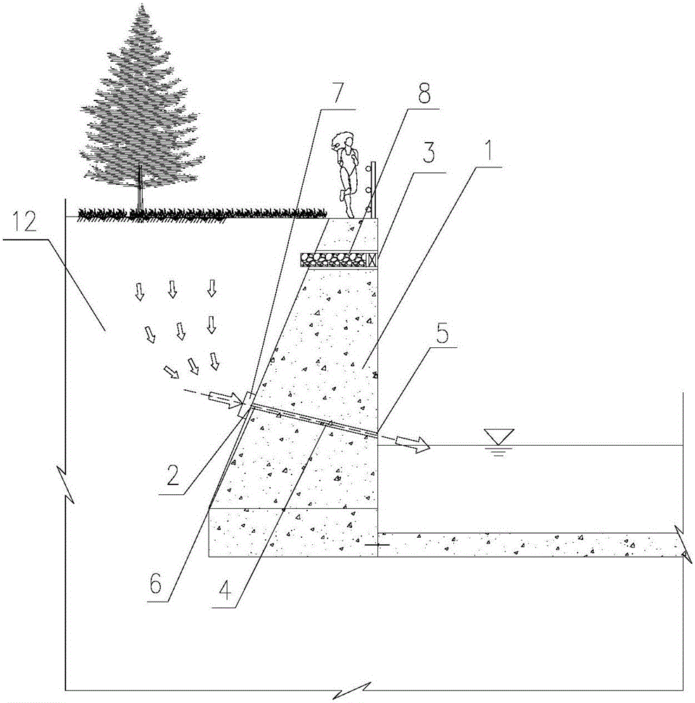
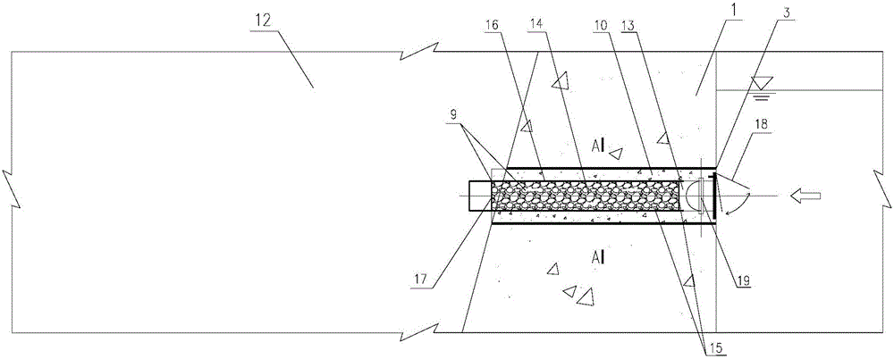
[0020] Such as figure 1 , figure 2 as well as image 3 Shown is a kind of rainwater provided by the present invention, which can input water flow into the dam body on both sides of the river, and when there is drought and water shortage, there can be a retaining wall structure used for sponge city construction to make the water storage of the dam body on both sides of the river input into the river. . The retaining wall structure includes a concrete or masonry retaining wall structure body 1, and the retaining wall structure also includes a drainage system 2 and a reverse permeable system 3, and the drainage system 2 is arranged vertically on the The middle and lower part of the concrete or masonry retaining wall structure body 1, and the reverse permeable system 3 is vertically arranged at the middle and upper part of the concrete or masonry retaining wall structure body 1. In the above, a set of drainage system 2 is arranged in the middle and lower part of the concrete o...


PUM


Abstract

The invention discloses a retaining wall structure, particularly discloses a retaining wall structure for sponge city construction, and belongs to the technical field of city landscape and river regulation structures. By means of the retaining wall structure for sponge city construction, water can be delivered to dams on the both sides of a river channel on rainy days, and water stored in the dams on the both sides of the river channel can be delivered to the river channel in case of water shortage in the drought period. The retaining wall structure comprises a concrete or slurry stone-laying retaining wall structure body, and further comprises a drainage system and a reverse water permeation system. The drainage system is arranged on the middle lower portion of the concrete or slurry stone-laying retaining wall structure body in the vertical direction. The reverse water permeation system is arranged on the middle upper portion of the concrete or slurry stone-laying retaining wall structure body in the vertical direction.

Description

technical field [0001] The invention relates to a retaining wall structure, in particular to a retaining wall structure used for sponge city construction, and belongs to the technical field of urban landscape and river channel regulation buildings. Background technique [0002] Traditional urban construction ideas emphasize hardening the water surface as much as possible, isolating water flow, and preventing seepage, including road surfaces, river channels, especially the bottom plates of river channels, and retaining walls on both banks. As a result, runoff, that is, the flow of surface water, has been greatly increased, and the water tolerance and elasticity of cities, especially along river channels, have been reduced. What's more serious is that the river bed and slopes were often closed and solidified in the past river course improvement, which made it impossible for the water flow to communicate with the outside world when flowing through the urban area, cutting off th...

Claims


Application Information

Patent Timeline
IPC IPC(8): E02B3/06E02B11/00
CPCE02B3/066E02B11/00
Inventor 刘畅
Owner POWERCHINA CHENGDU ENG
Why Eureka
Try Eureka