
Monitoring mechanism for fan

A technology of fans and fan covers, applied in mechanical equipment, engine components, machines/engines, etc., can solve the problem of the fan's inability to dissipate heat and personal safety, and achieve the effect of convenient assembly and disassembly, and avoid damage.

Inactive Publication Date: 2016-10-26
CHONGQING KAILONG TECH
View PDF0 Cites 0 Cited by
  • Summary
  • Abstract
  • Description
  • Claims
  • Application Information

AI Technical Summary

Problems solved by technology

[0004] The present invention intends to provide a monitoring mechanism for fans to solve the problem of personal safety caused by the failure of fans on traditional fan cover components to dissipate heat

Method used


Image

  • Monitoring mechanism for fan

Examples


Embodiment Construction

[0013] The present invention will be described in further detail below by means of specific embodiments:

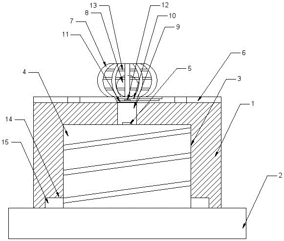
[0014] The reference signs in the drawings of the description include: fan cover assembly 1, flameout switch 2, positioning hole 3, circular boss 4, first trigger switch 5, fan 6, arc plate 7, sphere 8, groove 9, The first movable plate 10, the second movable plate 11, the second trigger switch 12, the iron chain 13, the positioning groove 14, and the positioning protrusion 15.

[0015] The embodiment is basically as attached figure 1 Shown: the monitoring mechanism for the fan, including the fan 6 cover assembly 1 and the flameout switch 2, the bottom of the fan 6 cover assembly 1 is provided with a positioning hole 3 for the flameout switch 2, and the flameout switch 2 is provided with a circular boss 4 and the first trigger switch 5, the inner wall of the positioning hole 3 is provided with an internal thread, and the outer wall of the circular boss 4 is provided with...


PUM


Abstract

The invention discloses a monitoring mechanism for a fan. The monitoring mechanism comprises a fan housing assembly and a shutdown switch, wherein a locating hole for the shutdown switch is formed in the bottom of the fan housing assembly, the shutdown switch is provided with a round boss and a first trigger switch, the inner wall of the locating hole is provided with an internal thread, and the outer wall of the round boss is provided with an external thread; the top of the fan housing assembly is provided with a fan electrically connected with a gasoline engine starting switch, and the fan is provided with a limiting frame in which a ball is arranged; and a groove capable of placing the ball is formed in the middle of the fan, the top of the groove is provided with a first movable plate and a second movable plate electrically connected with the gasoline engine starting switch, the first movable plate is located below the second movable plate, the first movable plate is provided with a second trigger switch, and the bottom of the groove communicates with the first trigger switch. According to the scheme, the monitoring mechanism is mainly used for solving the personal safety problem caused by heat radiation incapability of the fan on the traditional fan housing assembly.

Description

technical field [0001] The invention belongs to the field characterized by mechanical control connection, and specifically relates to a monitoring mechanism for a fan. Background technique [0002] The flameout switch is an important document to control the flameout of the general gasoline engine, and it is usually installed on the fan cover assembly. At present, the assembly hole on the flameout switch and the fan cover assembly is an interference fit, that is, the assembly hole is punched out on the casing of the fan cover assembly, and the flameout switch is knocked into the assembly hole by a rubber hammer. [0003] A fan is installed on the fan cover assembly, usually the fan is driven by the start switch of the gasoline engine, and the fan mainly plays a cooling role for the engine of the gasoline engine, but the fan cover assembly and the flameout switch are installed inside the gasoline engine. unobservable. The high-speed operation of the engine will generate a lo...

Claims


Application Information

Patent Timeline
Patent Type & Authority Applications(China)
IPC IPC(8): F01P5/02F01P11/14
CPCF01P5/02F01P11/14
Inventor 涂国荣徐飞林锋周玉明涂鑫豪
Owner CHONGQING KAILONG TECH
Learn More