
Load-bearing unit guide rail transfer equipment and method

A kind of guide rail and load transfer technology, applied in the direction of mechanical equipment, bearings, shafts and bearings, etc., can solve the problems of heavy guide rails of load-bearing units, difficult to guarantee repeatability, and equipment damage.

Active Publication Date: 2019-01-25
QINGDAO JINGUANGHONG INTELLIGENT MACHINERY ELECTRONICS CO LTD
View PDF7 Cites 0 Cited by
  • Summary
  • Abstract
  • Description
  • Claims
  • Application Information

AI Technical Summary

Problems solved by technology

[0002] When the spraying device is spraying on the fixed guide rail (about 13.5 meters) in the shelter, due to space constraints, the working state and transportation state of the spraying device are not in the same position, and the position of the load-bearing unit guide rail needs to be moved. Moving will cause the following problems: the guide rail of the load-bearing unit (single section 1.5m) is heavy and difficult to move; during the movement, it is easy to cause damage to the equipment; personal safety is difficult to guarantee; when returning to the working position, the repeatability is difficult to guarantee

Method used


Image

  • Load-bearing unit guide rail transfer equipment and method
  • Load-bearing unit guide rail transfer equipment and method

Examples


Embodiment Construction

[0028] In order to make the object, technical solution and advantages of the present invention clearer, the present invention will be further described in detail below in conjunction with specific embodiments and with reference to the accompanying drawings.

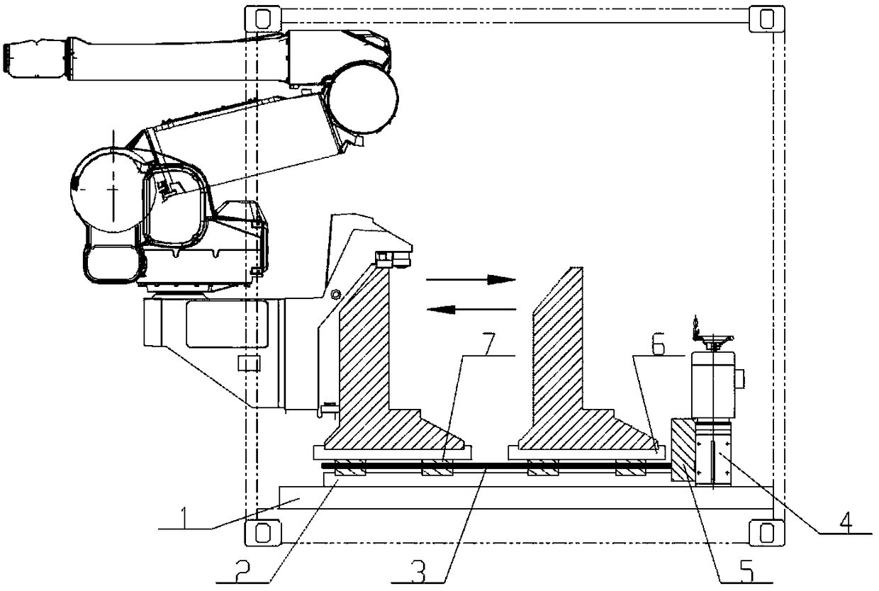
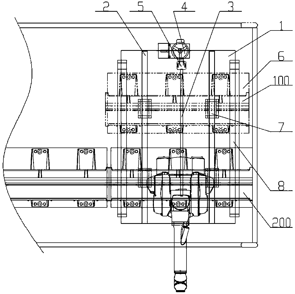
[0029] Such as figure 1 As shown, the present invention proposes a load-bearing unit guide rail transfer device, which includes a base 1, a linear slide rail 2, a ball screw 3, a reduction motor 4, a coupling 5, a bottom plate 6, a slider 7, and the like.

[0030] Among them, the base 1 is fixed on the installation position of the shelter bottom plate by bolts, and the linear slide rail 2 and the reduction motor 4 are respectively fixed on the base 1 by bolts. Fastened with bolts. Loosen the bolts on the bottom plate 6 and the base 1 when it needs to be transferred, and then it can be moved. The guide rail of the load-bearing unit at the bottom of the spraying device is connected to the bottom plate 6 by bolts, the slid...


PUM


Abstract

The invention discloses a load-bearing unit guide rail transfer device and method. The load-bearing unit guide rail transfer equipment includes: a base, a linear slide rail, a ball screw, a geared motor, a coupling, a guide rail bottom plate, and a slider; wherein, the linear slide rail and the geared motor are respectively fixed on the base, and the load-bearing unit The guide rail is located on the bottom plate of the guide rail, and the slider is fixed on the bottom of the guide rail bottom plate. The slider can slide on the linear slide rail. The ball screw and the deceleration motor are connected through a coupling. When the deceleration motor starts, it drives the ball screw to rotate, and the ball screw on The bottom plate of the driven guide rail slides on the linear slide rail through the slider, and the support plates are on both sides below the guide rail, and support the guide rail during the transplanting process.

Description

technical field [0001] The invention relates to the technical field of painting, in particular to a load-bearing unit guide rail transfer device and method. Background technique [0002] When the spraying device is spraying on the fixed guide rail (about 13.5 meters) in the shelter, due to space constraints, the working state and transportation state of the spraying device are not in the same position, and the position of the load-bearing unit guide rail needs to be moved. Moving will cause the following problems: the guide rail of the load-bearing unit (single section 1.5m) is heavy and difficult to move; during the moving process, it is easy to cause damage to the equipment; personal safety is difficult to guarantee; when returning to the working position, the repeatability is difficult to guarantee. Contents of the invention [0003] In view of this, the present invention proposes a load-bearing unit guide rail transfer equipment and method. In the present invention, th...

Claims


Application Information

Patent Timeline
Patent Type & Authority Patents(China)
IPC IPC(8): F16H25/22F16C29/02B05B13/04B05B15/00
CPCB05B13/04B05B15/00F16C29/02F16H25/2209
Inventor 来刚
Owner QINGDAO JINGUANGHONG INTELLIGENT MACHINERY ELECTRONICS CO LTD
Learn More