Eureka AIR delivers breakthrough ideas for toughest innovation challenges, trusted by R&D personnel around the world.

Cigarette lighter structure with charging function

A charging function, cigarette lighter technology, applied in the direction of collector, combustion ignition, incandescent ignition, etc., can solve the problems of easy loss, collision damage, etc., to achieve the effect of convenient implementation and simple design requirements

Active Publication Date: 2016-10-26
浙江致威电子科技有限公司
View PDF14 Cites 3 Cited by
  • Summary
  • Abstract
  • Description
  • Claims
  • Application Information

AI Technical Summary

Problems solved by technology

[0005] Therefore, the technical problem to be solved by the present invention is to overcome the problem that the car power adapter in the prior art is a separate device. When it is not necessary to charge the electronic product, it needs to be pulled out from the power socket at the position of the cigarette lighter, resulting in easy loss Or the technical defect of collision damage, so as to provide a cigarette lighter structure with charging function that does not need to be pulled out from the power socket when it is not necessary to charge the electronic product, so it will not be lost or collision damage will occur

Method used


Image

  • Cigarette lighter structure with charging function
  • Cigarette lighter structure with charging function
  • Cigarette lighter structure with charging function

Examples


Embodiment

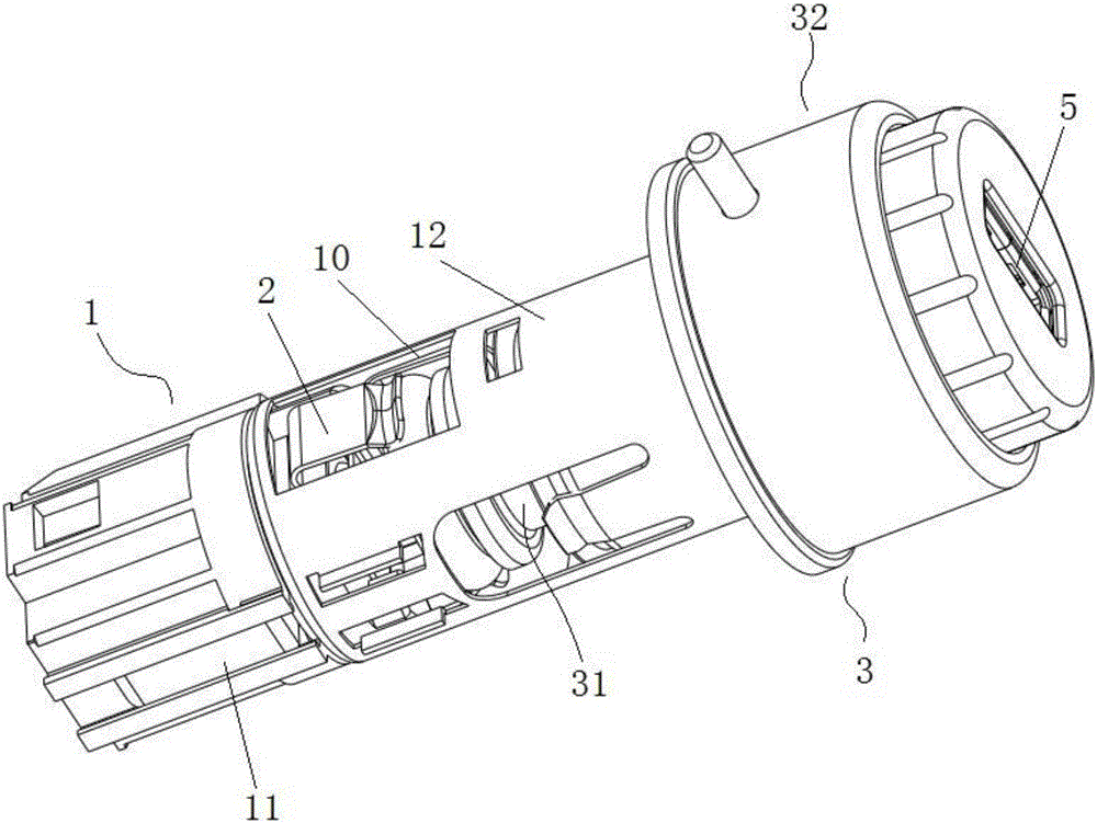
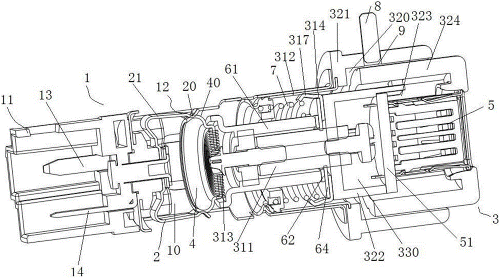
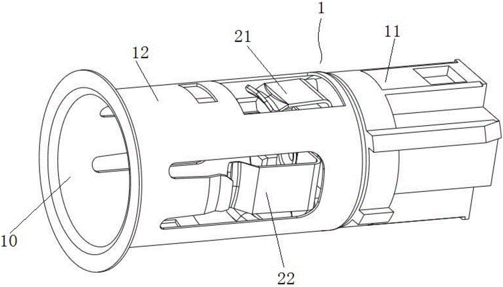
[0061] This embodiment provides a cigarette lighter structure with charging function, such as Figure 1-2 As shown, it includes: a base 1 with a mounting end 11 and an accommodating end 12; the mounting end 11 is suitable for being fixedly mounted on a vehicle, and is provided with a first electrode 13 and a second electrode suitable for being electrically connected to a vehicle power supply 14; the receiving end 12 is electrically connected to the first electrode 13, and has a receiving cavity 10; the power-taking piece 2 is installed inside the receiving cavity 10, and is electrically connected to the second electrode 14; point The cigarette holder 3 has a heating part 31 that can be inserted into the interior cavity 10, and a charging part 32 connected to the heating part 31; the heating part 31 is provided with a heating basin 4, and the heating basin 4 Opposite to the power-taking sheet 2; the charging part 32 is provided with a charging socket 5; the first power-taking s...


PUM


Abstract

The invention provides a cigarette lighter structure with a charging function. The cigarette lighter structure comprises a base and a cigarette lighter, wherein a first electrode and a second electrode suitable for being electrically connected with a vehicle-mounted power supply are arranged on the base; an accommodating end is electrically connected with the first electrode; an electricity-taking sheet installed in an accommodating inner cavity of the accommodating end is electrically connected with the second electrode; the cigarette lighter is provided with a heating part, a charging part, a first electricity-taking structure and a second electricity-taking structure; one end of the first electricity-taking structure is electrically connected with a heating basin, the other end of the first electricity-taking structure is electrically connected with the accommodating end, one end of the second electricity-taking structure is electrically connected with the electricity-taking sheet, and the other end of the second electricity-taking structure is electrically connected with the accommodating end through a charging socket; when the heating part is located at a first plugging position, the electricity-taking sheet contacts with the heating basin, and at this moment, the cigarette lighter structure enters a cigarette lighting mode; and when the heating part is located at a second plugging position, the electricity-taking sheet contacts with the second electricity-taking structure, and at this moment, the cigarette lighter structure enters a charging mode. According to the cigarette lighter structure disclosed by the invention, the charging socket is integrated on the cigarette lighter; and the two working modes are provided, thus great convenience is brought to use of people.

Description

technical field [0001] The invention relates to the technical field of cigarette lighters for automobiles, in particular to a structure of a cigarette lighter with a charging function. Background technique [0002] Cigarette lighter is a long-established configuration on the car. Its original intention was to facilitate drivers to light cigarettes while driving. With the widespread use of digital appliances such as mobile phones, some chargers that take power through cigarette lighters have begun to appear, which is convenient for people to charge digital appliances such as mobile phones in the car. [0003] Chinese patent document CN201490881U discloses a vehicle power adapter, which is composed of a vehicle power plug, an electronic product connector and an internal circuit. The output port can be applied to charge all electronic products with USB charging function, such as mobile phones, PSPs, cameras, etc., which brings convenience to people's use. [0004] However, th...

Claims


Application Information

Patent Timeline
Patent Type & Authority Applications(China)
IPC IPC(8): F23Q7/00F23Q7/22B60N3/14B60R16/02H02J7/00
CPCB60N3/14B60R16/02F23Q7/00F23Q7/22H02J7/0042
Inventor 赵顺荣
Owner 浙江致威电子科技有限公司
Why Eureka
Eureka Blog
Learn More