Control method used for while-drilling tube following pile machine

A control method and technology of pipe-while-drilling, which is applied to the automatic control system of drilling, drilling equipment and methods, sheet pile walls, etc., can solve the large difference in bearing performance between individual pipe pile foundations, which is not in line with the development of building industrialization Trend, damage to pipe piles and pile driver equipment, etc., to overcome the time lag and dependence on the technical level of engineers, to facilitate accurate design, and to increase the effect of sinking resistance

Active Publication Date: 2020-07-24
GUANGZHOU INSTITUTE OF BUILDING SCIENCE CO LTD
View PDF4 Cites 1 Cited by
  • Summary
  • Abstract
  • Description
  • Claims
  • Application Information

AI Technical Summary

Problems solved by technology

[0005] In order to solve the above-mentioned problems, the present invention aims to provide a control method for the pipe pile machine while drilling, to solve the problem that the manual operation of the pipe pile machine while drilling depends on the engineer's experience, and the time lag is easy to match the pipe pile and the pile machine equipment. Technical problems that cause damage and do not conform to the development trend of construction industrialization, and the bearing performance of individual pipe pile foundations after construction is quite different

Method used


Image

  • Control method used for while-drilling tube following pile machine
  • Control method used for while-drilling tube following pile machine
  • Control method used for while-drilling tube following pile machine

Examples


Embodiment 1

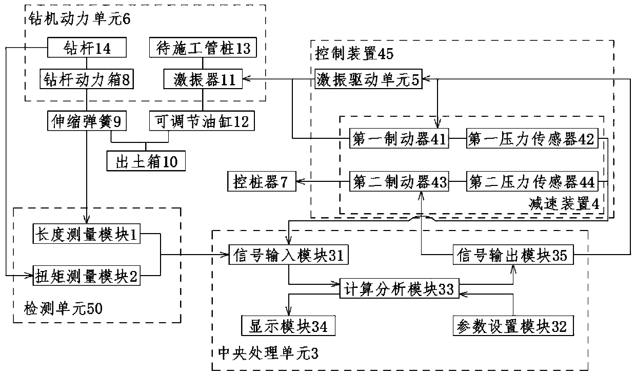
[0032] A kind of automatic control system that is used for drilling and following pipe pile machine is provided in the present embodiment, such as figure 1 As shown, it includes a detection unit 50 , a central processing unit 3 , a control device 45 and a drilling rig power unit 6 .

[0033] The drill power unit 6 includes a drill pipe 14, a drill pipe power box 8 corresponding to the drill pipe 14, a pipe pile 13 to be constructed, and a vibrator 11 corresponding to the pipe pile 13 to be constructed; The power box 8 is connected with an excavation box 10 by connecting a telescopic spring 9, and the excavation box 10 is connected with the vibrator 11 by connecting an adjustable oil cylinder 12.

[0034] The detection unit 50 is arranged between the central processing unit 3 and the drilling rig power unit 6, and is used to detect the operating parameters of the drilling rig power unit 6 and send the operating parameters to the central processing unit 3; The detection unit in...

Embodiment 2

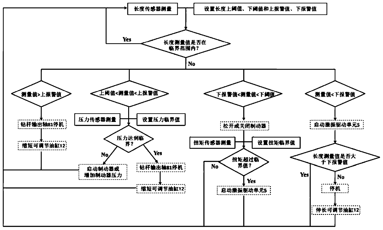
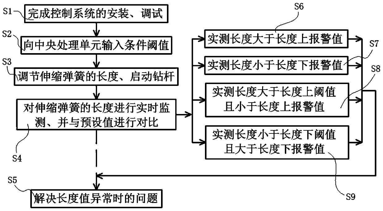
[0044] In order to facilitate the understanding of the working principle of the above-mentioned automatic control system, in this embodiment, a method such as Figure 2-Figure 3 The shown control method for drilling and following pipe pile machine includes the following steps:

[0045] S1. Complete the installation and debugging of the above-mentioned automatic control system before construction.

[0046] S2. Input to the central processing unit 3 the condition thresholds for controlling the output shaft 81 of the drill pipe power box 8, the reduction gear 4 and the excitation drive unit 5 to start and stop, including a pressure critical value, a torque early warning value, a length upper threshold, Length lower threshold, length upper alarm value, length lower alarm value and buffer time; wherein, length upper alarm value > length upper threshold > length lower threshold > length lower alarm value.

[0047] S3. Adjust the adjustable oil cylinder 12 so that the length of the ...


PUM


Abstract

The invention discloses a control method used for a while-drilling tube following pile machine. The method comprises the steps of S1, finishing mounting and debugging of an automatic control system; S2, inputting condition threshold values used for controlling an output shaft of a drilling rod power box, a speed reduction device and a shock excitation driving unit to be started and stopped into acentral processing unit; S3, adjusting an adjusting oil cylinder to enable the length of a telescopic spring to be within the length upper threshold value and length lower threshold range, and starting a drilling rod for carrying out construction; S4, in the constructing process, carrying out real-time monitoring on the length of the telescopic spring, and comparing the actually measured length ofthe telescopic spring with the preset threshold value; and S5, when a comparison value is abnormal, taking processing measures in time, and ensuring normal operation of the construction. Time lay ofmanual operation and dependency on technical levels of an engineer can be overcome, the development tendency of the building industrialization can be met, the bearing property difference between pipefile foundation units after construction is finished is small, precise design of a building foundation and a structure is facilitated, and the later-period detection and maintaining are facilitated.

Description

technical field [0001] The invention belongs to the technical field of foundation and foundation engineering, and in particular relates to a control method for a follow-up pipe pile machine while drilling. Background technique [0002] Prestressed high-strength concrete pipe piles have been widely used in bridges, ports, industrial and civil buildings and other projects because of their advantages in quality stability, unit bearing capacity and cost, and are more in line with the development trend of building industrialization. In the traditional hammering method construction, the complex elastic wave response generated during the contact between the heavy hammer and the pile head will cause damage to the concrete of the pile body, and its noise pollution is another obstacle to further promotion in urban areas. However, the static pressure method will not produce noise and vibration pollution during the construction process, and the bearing capacity of the pile foundation ca...

Claims


Application Information

Patent Timeline
Patent Type & Authority Applications(China)
IPC IPC(8): E02D7/00E02D5/58E21B44/00E21B7/20
CPCE02D7/00E02D5/58E21B44/00E21B7/20Y02P90/02
Inventor 陈航胡贺松唐孟雄
Owner GUANGZHOU INSTITUTE OF BUILDING SCIENCE CO LTD
Why Eureka
Try Eureka