A polarization-insensitive microring filter based on a silicon nanowire waveguide
A polarization-insensitive, silicon nanowire technology, used in instruments, light guides, optics, etc., can solve problems such as increasing system complexity and device size, reducing complexity and improving flexibility.
- Summary
- Abstract
- Description
- Claims
- Application Information
AI Technical Summary
Problems solved by technology
Method used
Image

Examples
Embodiment 1
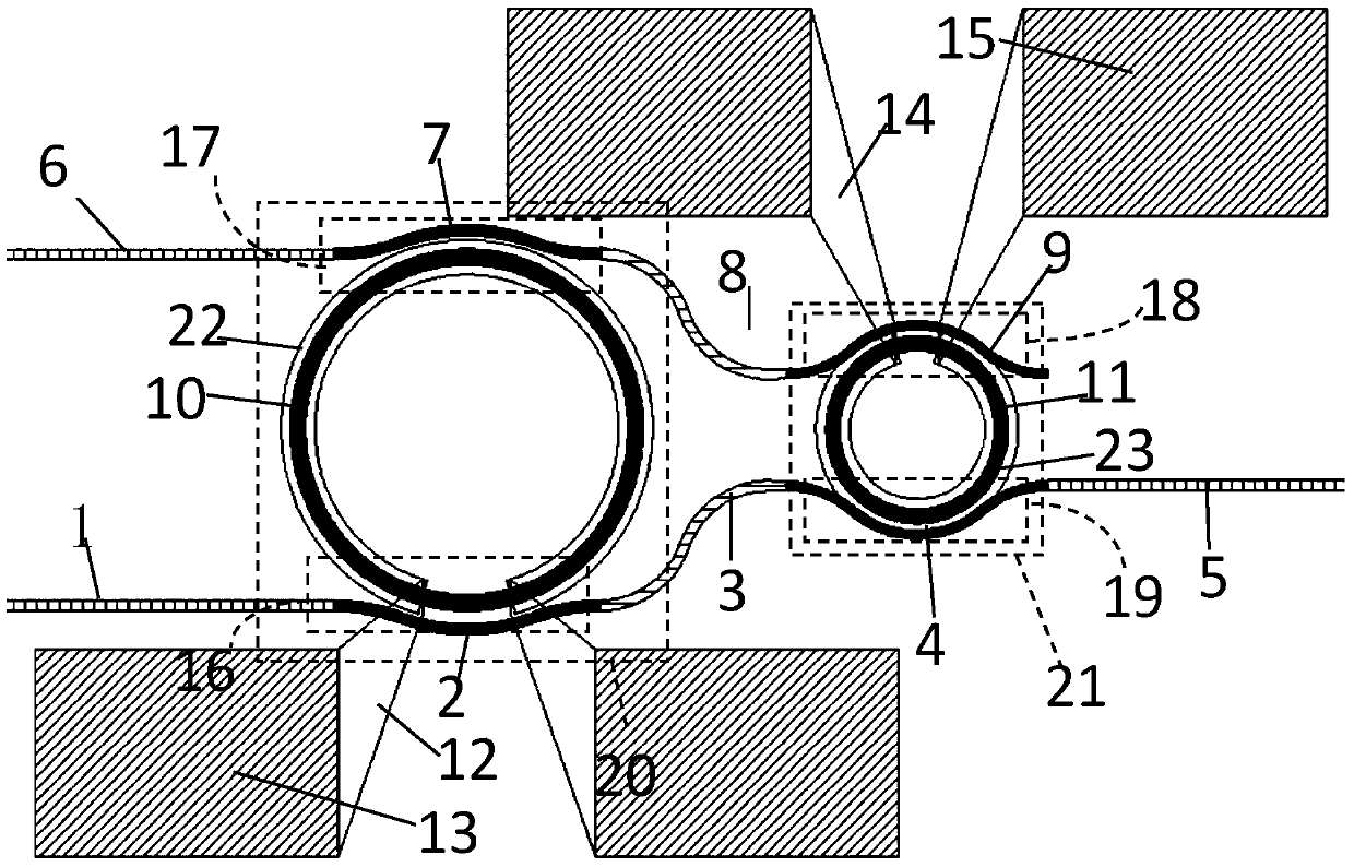
[0037] Such as figure 1 As shown, the first embodiment includes a connected first microring filter 20 and a second microring filter 21 and metal electrodes, the first microring filter 20 includes a first ring waveguide 10 and a symmetrically placed ring waveguide The first curved waveguide 2 and the third curved waveguide 7 on both sides of 10, the microring adopts a single first ring waveguide 10, and the second microring filter 21 includes the second ring waveguide 11 and the second The second curved waveguide 4 and the fourth curved waveguide 9 on both sides of the ring waveguide 11, wherein the micro-ring adopts a single second ring waveguide 11. The first ring waveguide 10 and the second ring waveguide 11 adopt a single microring structure.
[0038] The input waveguide 1, the first curved waveguide 2, the first adiabatic connection waveguide 3, the second curved waveguide 4 and the first output waveguide 5 are connected end to end, and are located on the same side of the...
Embodiment 2
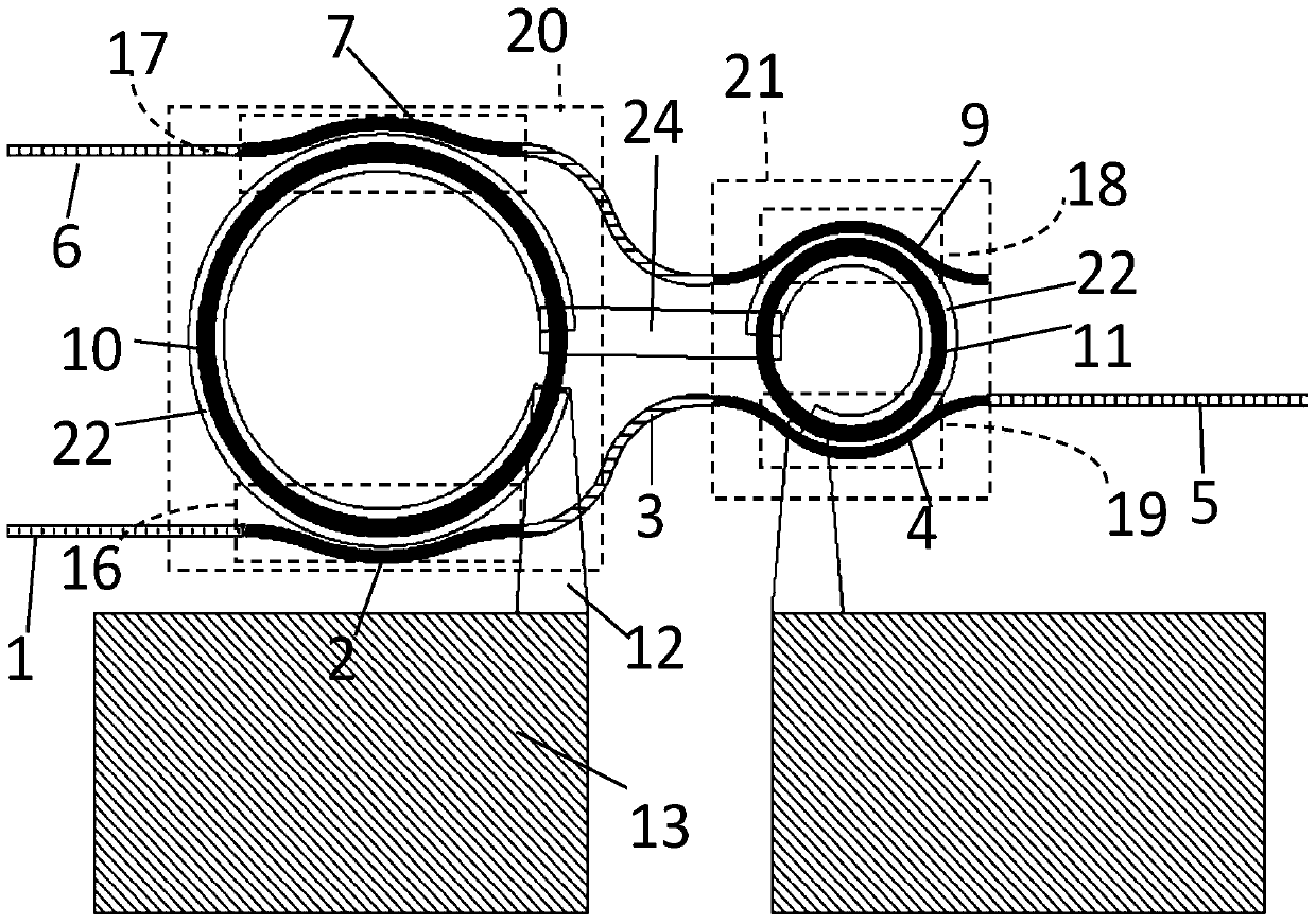
[0045] Such as figure 2 As shown, the second embodiment includes a connected first microring filter 20 and a second microring filter 21 and metal electrodes. The first microring filter 20 includes a first ring waveguide 10 and a symmetrically placed ring waveguide The first curved waveguide 2 and the third curved waveguide 7 on both sides of 10, the microring adopts a single first ring waveguide 10, and the second microring filter 21 includes the second ring waveguide 11 and the second The second curved waveguide 4 and the fourth curved waveguide 9 on both sides of the ring waveguide 11, wherein the micro-ring adopts a single second ring waveguide 11. The first ring waveguide 10 and the second ring waveguide 11 adopt a single microring structure.
[0046] The input waveguide 1, the first curved waveguide 2, the first adiabatic connection waveguide 3, the second curved waveguide 4 and the first output waveguide 5 are connected end to end, and are located on the same side of t...
Embodiment 3
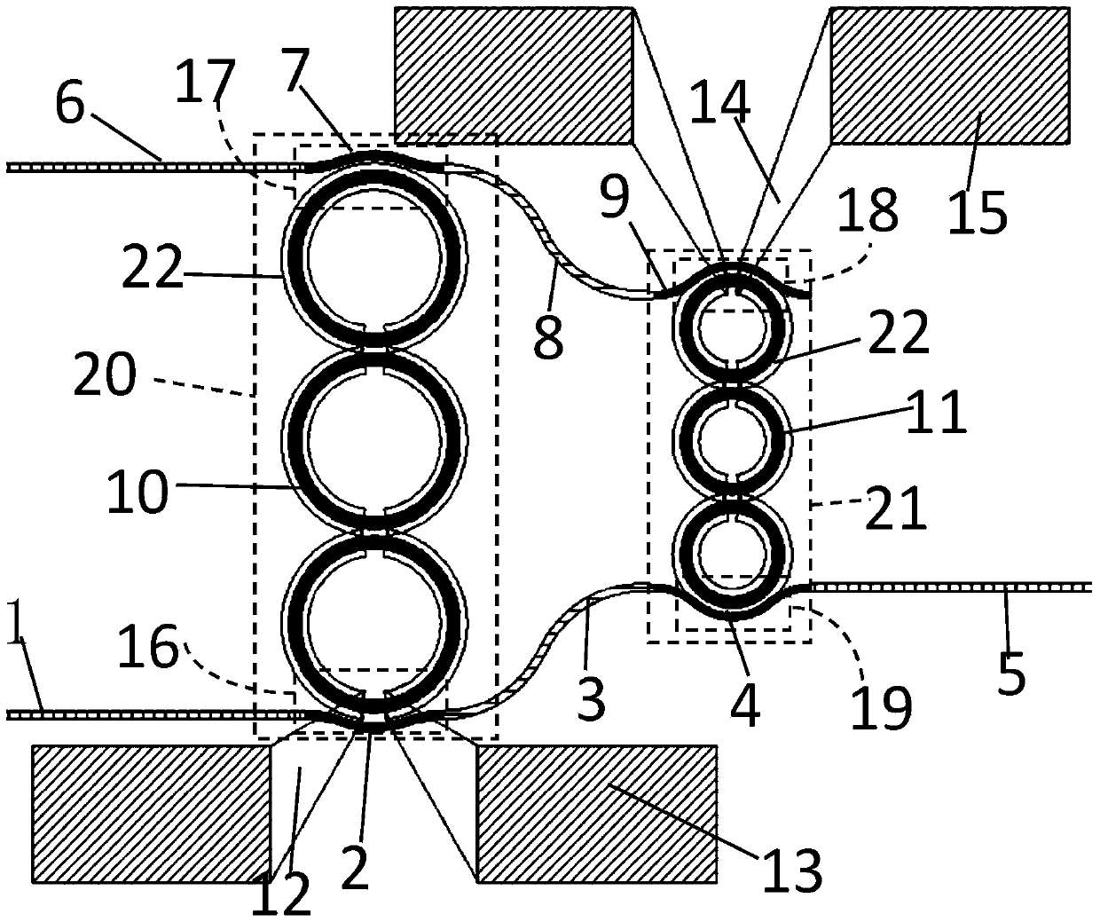
[0049] Such as figure 1 As shown, the third embodiment includes a first micro-ring filter 20, a second micro-ring filter 21 and metal electrodes connected to each other. The first micro-ring filter 20 includes three cascaded first ring waveguides 10 and symmetrically arranged The first curved waveguide 2 and the third curved waveguide 7 on both sides after cascading the first ring waveguide 10, the second microring filter 21 includes three cascaded second ring waveguides 11 and the second ring waveguide symmetrically placed 11 After cascading, the second curved waveguide 4 and the fourth curved waveguide 9 on both sides. The first ring waveguide 10 and the second ring waveguide 11 adopt a cascaded structure of multiple microrings.
[0050] The input waveguide 1, the first curved waveguide 2, the first adiabatic connection waveguide 3, the second curved waveguide 4 and the first output waveguide 5 are connected end to end, and are located on the same side after the first ring ...
PUM
 Abstract
Description
Claims
Application Information