Alignment method and alignment system

A technology of alignment marks and substrates, which is applied in the direction of optics, instruments, and photoplate-making processes on patterned surfaces, etc., can solve problems such as large errors, grafting, and low alignment efficiency, so as to improve the success rate, increase production capacity, and improve The effect of alignment efficiency

Inactive Publication Date: 2016-10-26
BOE TECH GRP CO LTD +1
View PDF5 Cites 15 Cited by
  • Summary
  • Abstract
  • Description
  • Claims
  • Application Information

AI Technical Summary

Problems solved by technology

For irregular defects, only manual alignment can be used. The error of manual alignment is relatively large, and the alignment efficiency is low, resulting in insufficient weaving.

Method used


Image

  • Alignment method and alignment system
  • Alignment method and alignment system
  • Alignment method and alignment system

Examples


Embodiment Construction

[0047] In order for those skilled in the art to better understand the technical solution of the present invention, the alignment method and the alignment system provided by the present invention will be described in detail below in conjunction with the accompanying drawings.

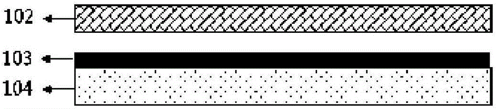
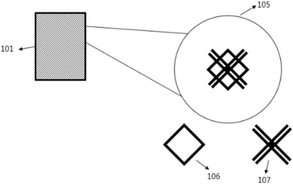
[0048] Such as figure 1 As shown, the substrate 103 is placed on a workbench 104 , and a mask 102 is disposed above the substrate 103 for exposing the substrate 103 . Before exposure, the positions of the substrate 103 and the mask plate 102 need to be matched. The specific matching method is: the substrate 103 and the mask plate 102 respectively have multiple alignment areas, and each alignment area is provided with an alignment The mark is used as an alignment reference between the substrate 103 and the mask plate 102 . For example, if figure 2 As shown, the alignment mark on the substrate 103 is in the shape of "#"; the alignment mark on the mask plate 102 is in the shape of a diamond. In this cas...


PUM


Abstract

The invention provides an alignment method and an alignment system. The alignment method includes: 1) a collection step, collecting the images in all alignment zones; 2) a determination step: determining whether the matching degrees of alignment markers in all images reach a preset standard, and if true, performing an alignment step according to the all alignment zones, or otherwise, performing a screening step; 3) the screening step: screening at least one alignment zone, of which the matching degree is highest, from all alignment zones, and performing the alignment step according to the screened at least one alignment zone; 4) the alignment step: aligning the alignment markers on a substrate with the alignment markers on a mask plate to match the substrate with the mask plate in position. The alignment method can increase success rate of automatic alignment, so that not only is interlayer alignment deviation due to excessive high alignment error avoided, but also alignment efficiency is increased, thereby increasing productivity.

Description

technical field [0001] The present invention relates to the field of display technology, in particular to an alignment method and an alignment system. Background technique [0002] In the yellow light process, when the exposure machine performs the second layer process on the substrate, it usually uses the alignment camera to capture the alignment mark on the substrate to achieve the position matching of the substrate and the mask. [0003] Specifically, as figure 1 As shown, a substrate 103 is placed on a workbench 104, and a mask 102 is disposed above the substrate 103 for exposing the substrate. Such as figure 2 As shown, a diamond-shaped alignment mark 106 is provided on the alignment area of ​​the mask 102 , and correspondingly, a #-shaped alignment mark 107 is provided on the alignment area of ​​the substrate 103 . The alignment camera 101 of the exposure machine captures the image 105 of the above-mentioned alignment area, and a diamond-shaped alignment mark 106 a...

Claims


Application Information

Patent Timeline
Patent Type & Authority Applications(China)
IPC IPC(8): G03F9/00
CPCG03F9/7073
Inventor 王辉王志强张力舟高琪申洋李明龙王强
Owner BOE TECH GRP CO LTD
Why Eureka
Try Eureka