
Circuit breaker

A circuit breaker and circuit breaker body technology, which is applied in the direction of circuits, protection switch parts, electrical components, etc., can solve the problems that the circuit breaker body falls on the operator, injures the operator, and injures the user. Achieve the effects of improving convenience, preventing safety accidents, and improving use safety

Active Publication Date: 2016-10-26
HYUNDAI ELECTRIC & ENERGY SYST CO LTD
View PDF6 Cites 2 Cited by
  • Summary
  • Abstract
  • Description
  • Claims
  • Application Information

AI Technical Summary

Problems solved by technology

In this case, a safety accident may occur, for example, the breaker body falls before a part of the breaker body is inserted and the worker is injured, etc.
[0010] In addition, when the breaker body is drawn out from the inside of the case, that is, when the breaker body is separated from the inside of the case, if the breaker body is completely separated from the inside of the case at one time, it may occur that the breaker body falls. Safety accidents in which it falls on the operator and injures the user, etc.

Method used


Image

  • Circuit breaker
  • Circuit breaker
  • Circuit breaker

Examples


no. 1 approach

[0073] First, refer to Figure 1 to Figure 6 , the circuit breaker according to the first embodiment of the present invention will be described.

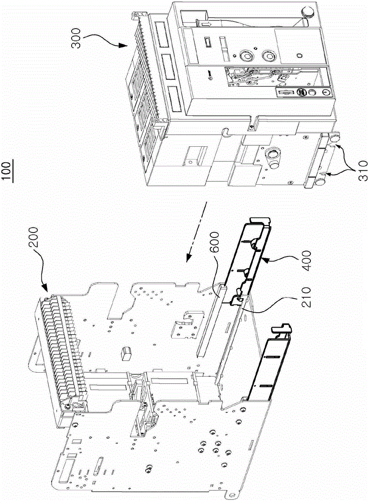
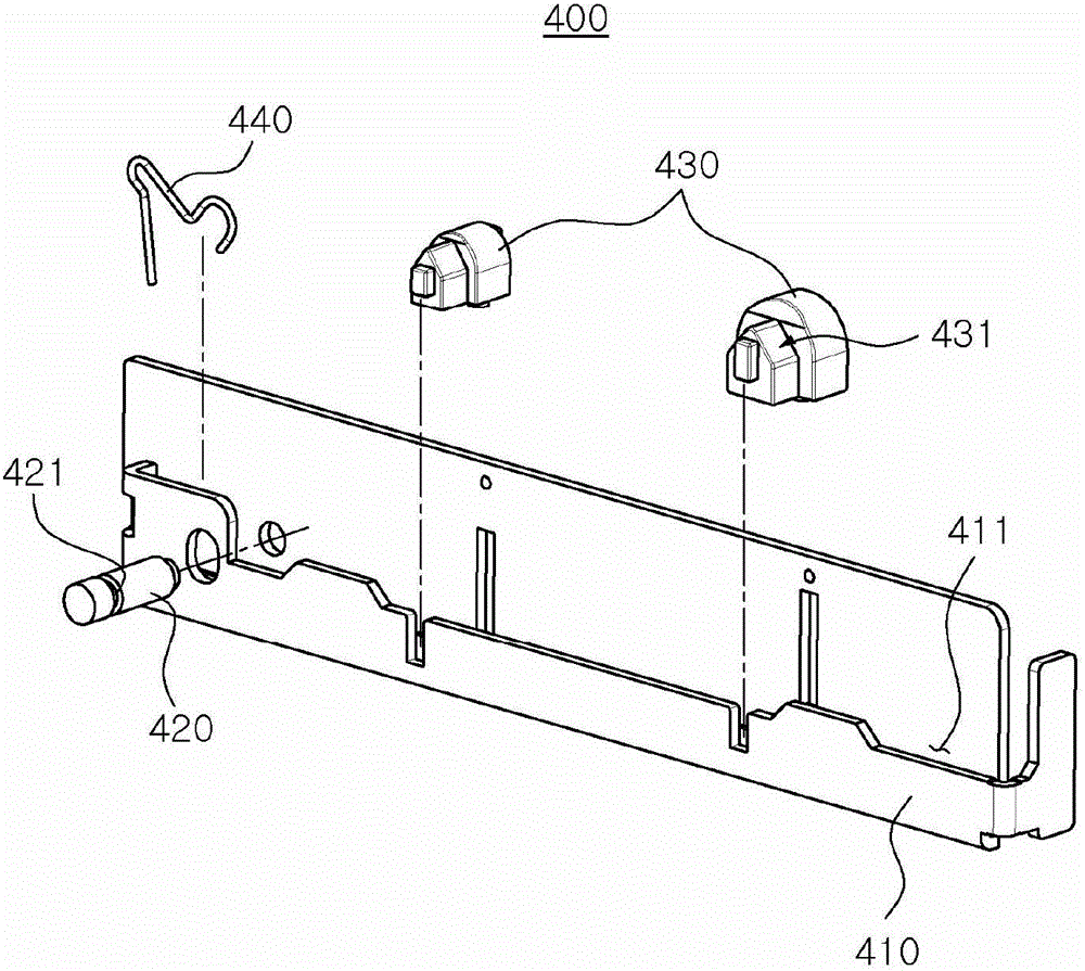
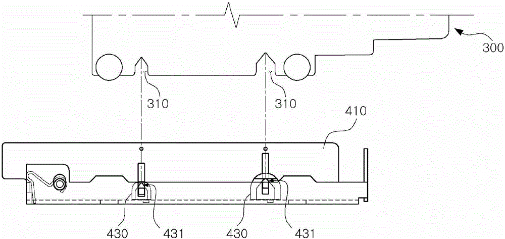
[0074] figure 1 is a perspective view of a circuit breaker according to a first embodiment of the present invention, figure 2 is a perspective view of a sliding unit of a circuit breaker according to a first embodiment of the present invention, image 3 It is a diagram showing a state in which a circuit breaker body of the circuit breaker according to the first embodiment of the present invention is connected to the movable bracket.

[0075] in addition, Figure 4 to Figure 6 is a state diagram of the operation of the circuit breaker according to the first embodiment of the present invention.

[0076] figure 1 A first embodiment of a circuit breaker 100 according to the invention is shown in . The circuit breaker body 300 is connected with a plurality of electrically driven mechanical parts, and the circuit breaker body 300 i...

no. 2 approach

[0101] Below, refer to Figure 7 to Figure 16 , the circuit breaker according to the second embodiment of the present invention will be described.

[0102] Figure 7 is a perspective view of a circuit breaker according to a second embodiment of the present invention.

[0103] also, Figure 8 is a view showing the main body drop-off prevention part of the circuit breaker according to the second embodiment of the present invention viewed from the outside of the case, where the case is indicated by a dotted line, Figure 9 It is a figure which shows the main body fall-off prevention part of the circuit breaker which concerns on 2nd Embodiment of this invention viewed from the inner side of a case.

[0104] in addition, Figure 10 to Figure 16 are diagrams each showing the operation of the circuit breaker according to the second embodiment of the present invention.

[0105] The circuit breaker 100 according to the second embodiment of the present invention may include a housi...


PUM


Abstract

The invention relates o a circuit breaker. According to one embodiment of the invention, the circuit breaker may includes: a housing; a circuit breaker body which is connected to the housing; and at least one of a slide unit and a body anti-disconnection portion, wherein the slide unit is connected to the circuit breaker body and can match a railway arranged on the housing to move so as to allow the circuit breaker body to move, and the body anti-disconnection portion is arranged on the housing and is configured to be clamped on the circuit breaker body so as to prevent disconnection of the circuit breaker from the housing.

Description

technical field [0001] The present invention relates to a circuit breaker (CIRCUIT BREAKER), more particularly, relates to a circuit breaker with a guide rail or when the circuit breaker body is drawn out from the case, the circuit breaker body cannot be separated from the case at one time. Background technique [0002] When a fault occurs in a power system, a high fault current equivalent to dozens of times the rated current may flow due to a sharp decrease in load resistance. In order to prevent the spread of the fault area and damage to other devices in the event of a power system accident, it is necessary to cut off the fault current by itself quickly. [0003] The circuit breaker used in this case is a device that automatically cuts off the circuit to prevent damage caused by overload or short circuit in the circuit. The reliability of the circuit breaker has a core influence on the reliability of the entire system. [0004] In particular, among such circuit breakers, ...

Claims


Application Information

Patent Timeline
Patent Type & Authority Applications(China)
IPC IPC(8): H01H71/02
CPCH01H71/0214H01H71/0228
Inventor 朴钟德柳在九
Owner HYUNDAI ELECTRIC & ENERGY SYST CO LTD
Learn More