
Sparkless socket

A non-sparking, socket technology, applied in the base/casing, coupling device, instrument, etc., can solve problems such as danger, user fear and fear, and achieve the effect of increasing safety

Active Publication Date: 2016-10-26
徐 政村
View PDF5 Cites 8 Cited by
  • Summary
  • Abstract
  • Description
  • Claims
  • Application Information

AI Technical Summary

Problems solved by technology

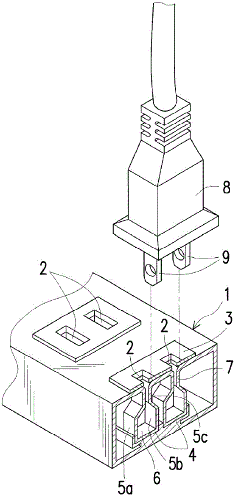
[0004] However, when the user inserts the two prongs 9 of the plug 8 into or pulls out the socket 7 through the socket 2, the two prongs 9 of the plug 8 contact / or pull out the first and second clips 5a, 5b. It is very easy to generate sparks at the moment, which is not only dangerous, but also makes users afraid

Method used


Image

  • Sparkless socket
  • Sparkless socket
  • Sparkless socket

Examples


Embodiment Construction

[0104] In order to make the content of the present invention more comprehensible, the following specific embodiments are taken as examples in which the present invention can indeed be implemented. In addition, where possible, elements / members / steps with the same reference numerals are used in the drawings and embodiments to represent the same or similar parts.

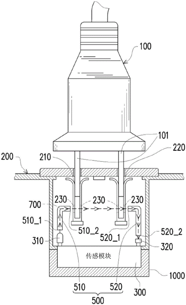
[0105] See below Figure 3 ~ Figure 6 , Figure 3 ~ Figure 6 It is the non-spark socket 1000 shown in the first embodiment of the present invention. The non-sparking socket 1000 can be inserted into a pair of pins 101 of the plug 100 . Non-spark socket 1000 comprises socket 200, sensor module 300, controller 400 and switch module 600 (as Figure 5 shown). The socket 200 has a first slot 210 and a second slot 220 inside. The walls of the first slot 210 and the second slot 220 are provided with through holes 230 that can communicate with each other.

[0106] The sensor module 300 is provided with a transmitter 310 ...


PUM


Abstract

The invention provides a sparkless socket. The sparkless socket including a socket, a sensing module, a controller and a switching module. The sensing module includes an emitter and a receiver. The emitter is used to emit an infrared light. The receiver is used to receive the infrared light emitted by the emitter through a light guide element module and holes on slots of the socket and generate a sensing result accordingly. The controller is coupled to the sensing module to receive the sensing result and is coupled to a city power system. The switch module is coupled between the socket and the controller to receive an AC power supplied by the city power system from the controller and is controlled by the controller to transfer the AC power to the socket. The controller judges whether a plug is inserted into the socket according to the sensing result and enables or disables the switching module. The invention can avoid the situation in which sparks are easily generated and dangerous at the moment when pins of the plug contact or are pulled out of a conductive clip inside the socket immediately, and the safety of the electric power is increased.

Description

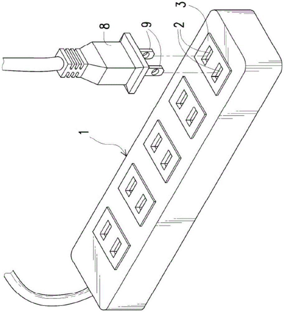
technical field [0001] The present invention relates to a socket, and in particular to a non-sparking socket. Background technique [0002] Common socket structures such as figure 1 , figure 2 shown. The socket structure includes a housing 1 . The casing 1 is provided with two insertion holes 2 parallel to each other and at least one base unit 3 . The base unit 3 is provided with two limiting slots 4 . Each limiting slot 4 is provided with a first clip 5a and a second clip 5b made of conductive material opposite to each other. The middle part of the first clamping piece 5a and the second clamping piece 5b is bent inwardly so that the distance between the first and second clamping pieces 5a, 5b is reduced to form a clamping portion 5c. The ends of the first and second clips 5a, 5b away from the socket 2 are connected to form an electrical terminal 6 . The power terminal 6 is used to connect to the mains. An open insertion port 7 is formed at one end of the first and ...

Claims


Application Information

Patent Timeline
Patent Type & Authority Applications(China)
IPC IPC(8): H01R27/00H01R13/66H01R13/70H01R13/703
CPCH01R13/7036G05B15/02H01R13/53H01R13/6683H01R13/717H01R2103/00H01R2105/00H01R27/00H01R13/66H01R13/70H01R13/703
Inventor 徐政村
Owner 徐 政村
Learn More