Cable wear tractioned cavity cleaning device

A cavity-cleaning and cable-clearing technology, which is applied in the direction of cable installation, cable installation devices, and cable laying equipment, can solve the problems of large pulling resistance, dead angles, and low work efficiency, so as to achieve smooth and stable operation, save construction costs, clean up effect

Active Publication Date: 2016-10-26
国网山东省电力公司昌乐县供电公司
View PDF8 Cites 5 Cited by
  • Summary
  • Abstract
  • Description
  • Claims
  • Application Information

AI Technical Summary

Problems solved by technology

Existing problems: First, the traction head is relatively bulky, the pulling resistance is large, and labor-intensive; especially when encountering debris attached to the pipe wall, it is easy to jam and work efficiency is low; second, the push-type cable The diameter of the tractor head for pipe cleaning is fixed. It is inconvenient to use the corresponding tractor head for different specifications of cable tubes. Moreover, it is difficult to grasp the size of the tractor head. The diameter of the puller head is larger. Although the cleaning effect is better, the It is easy to jam, resulting in poor operation; on the contrary, using a small diameter traction head, although the operation is smooth, but there will be dead corners, which will cause the problem of unclean cleaning; third, the cleaning area of ​​the inner wall of the cable tube can only reach half , it is difficult to meet the requirements of the construction standards for cable pipe penetration

Method used


Image

  • Cable wear tractioned cavity cleaning device
  • Cable wear tractioned cavity cleaning device
  • Cable wear tractioned cavity cleaning device

Examples


Embodiment Construction

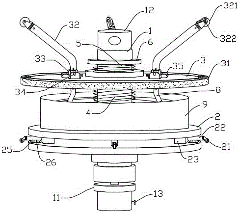
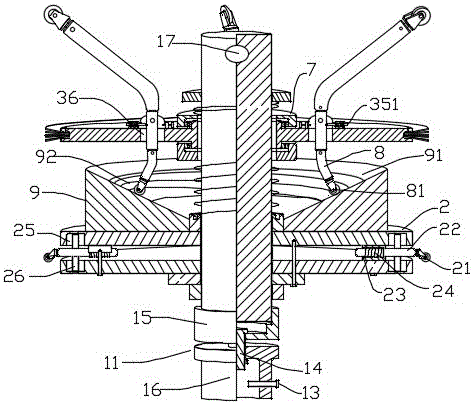
[0021] refer to figure 1 and figure 2 , the cable pipe traction cleaning device includes a main shaft made of a hard metal material with a diameter of 3 cm and a length of 20 cm. A cable connector 11 is provided at one end of the main shaft 1. The cable connector 11 shown in the figure includes a fixing bolt Head 15 and movable cap body 16; Fixed bolt head 15 plays a role of connection and fixation, and it is fastened and connected with main shaft 1 end by thread; Movable cap body 16 is movably connected with fixed bolt head 15 by connecting pin 14, and movable cap body 16 can Flexible rotation. The outer end of the movable cap body 16 is provided with a cable socket, and the movable cap body 16 is provided with a fixing bolt 13 for fixing the inserted cable. The other end of the main shaft 1 is a traction joint 12 , and a traction joint hole 17 is arranged on the traction joint 12 . The main shaft 1 is provided with a support plate 2 close to the cable connector 11 , and ...


PUM


Abstract

The invention discloses a cable wear tractioned cavity cleaning device comprising a main shaft. The two ends of the main shaft are respectively provided with a cable connector and a traction connecting head. The main shaft is provided with a support plate, and the circumference of the support plate is provided with rolling wheels. The main shaft is also provided with a cavity cleaning plate which is connected with the main shaft in a sliding manner. The cavity cleaning plate is provided with a driving arm; the driving arm is provided with a driving wheel; the driving wheel is arranged on the side with the exterior edge located outside of the cylindrical face formed during the rotation of the cavity cleaning plate. The invention is mainly used for laying underground power cables. It can not only be applied in large areas but it is also convenient to construct. With the functions of thorough cleaning, it is not easy to be jammed and can run smoothly. At the same time, for different cable pipes, all that needs to do is replace the cavity cleaning plate according to specific requirement, without the need to be equipped with a number of cavity cleaning plates, thus saving construction costs.

Description

technical field [0001] The invention belongs to the technical field of power cable laying construction tools, and in particular relates to a device used as a cable pulling head to clean the inner cavity of a cable pipe when underground power cables are laid through pipes. Background technique [0002] In the construction of electrical equipment, when the cables pass through buildings, obstacles and other places where the cables are easy to be damaged, it is necessary to bury the cable tubes underground so that the cables pass through the tubes to protect the cables. According to the requirements of construction standards, the inner cavity of the cable tube must be clean and free of debris. Existing construction of cables through pipes is generally guided by a gyro-shaped metal traction head, and the two ends of the traction head are respectively connected to the pull wire and the cable; During the running process, push the sundries in the threading pipe to run, and drive th...

Claims


Application Information

Patent Timeline
Patent Type & Authority Applications(China)
IPC IPC(8): H02G1/08H02G9/06
CPCH02G1/083H02G9/06
Inventor 刘树国张玉法郑冲郑文堂蔺雪震季强
Owner 国网山东省电力公司昌乐县供电公司
Why Eureka
Try Eureka