Speed switching circuit

A speed switch and circuit technology, applied in circuits, semiconductor devices, transistors, etc., can solve the problems of high current consumption, power loss of the whole vehicle, and difficulty in reaching 1 million times of service life. Effect

Inactive Publication Date: 2016-10-26
YUEQING MINGTU ELECTRIC TECH CO LTD
View PDF4 Cites 0 Cited by
  • Summary
  • Abstract
  • Description
  • Claims
  • Application Information

AI Technical Summary

Problems solved by technology

[0003] The eddy current retarder is generally controlled by a mechanical handle switch. If the mechanical handle does not return after the driver stops, the eddy current retarder will always be in working condition and consume a large amount of current, causing the vehicle to Power loss; in order to avoid this situation, a device such as a speed switch is introduced
[0004] The speed switch is used to control the eddy current retarder to avoid the eddy current retarder working when the vehicle speed is low or when the vehicle is stopped. The speed switch currently being used in the market uses a relay to control the eddy current retarder. The relay is generally only 100,000 The service life of the speed switch is 3 million times, even if a special customized relay is used, the service life is difficult to reach 1 million times

Method used


Image

  • Speed switching circuit
  • Speed switching circuit
  • Speed switching circuit

Examples


Embodiment

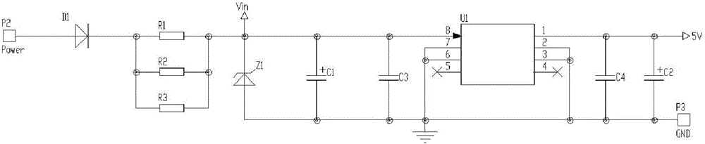
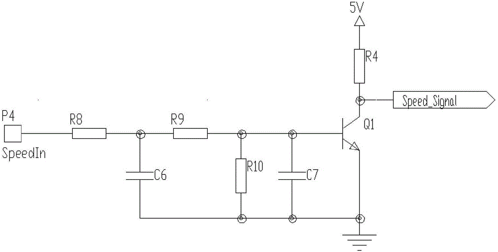
[0013] see Figure 1-4 , the present invention provides a technical solution: a speed switch circuit, including capacitor C1, capacitor C2, capacitor C3, capacitor C4, resistor R1, resistor R2, resistor R3, diode D1, regulator Z1, power chip U1 and triode Q1, one end of the four capacitors is grounded, the output of the voltage regulator transistor Z1 is grounded, one end of the resistor R1, resistor R2 and resistor R3 are connected in parallel to the output of the diode, and the other end is connected to the input of the voltage regulator transistor Z1, The voltage regulator tube Z1, capacitor C1 and capacitor C3 are connected in parallel, the input of the voltage regulator tube Z1 is connected to Vin and the Vin signal is input to the eighth pin of the power chip U1, and the second pin of the power chip U1 , the third pin, the sixth pin and the seventh pin are all grounded, the first pin of the power chip U1 is connected to one end of C2 and C4 to output a 5V signal, and the ...


PUM


Abstract

The invention discloses a speed switching circuit. The speed switching circuit comprises a microprogrammed control unit U2 and a power transistor Q2, wherein a capacitor C5 is connected between VDD and VSS of the microprogrammed control unit U2; a third pin, a sixth pin and a seventh pin of the microprogrammed control unit U2 are grounded respectively after passing through a resistor R11, a resistor R5 and a resistor R6; a fifth pin of the microprogrammed control unit U2 is connected with a 5V signal through a resistor R7; after a resistor R15, a capacitor C8 and a voltage-regulator tube Z2 are connected in parallel, one end of the resistor R15, one end of the capacitor C8 and one end of the voltage-regulator tube Z2 are connected with the power transistor Q2, and the other ends of the resistor R15, the capacitor C8 and the voltage-regulator tube Z2 are connected with a combination diode D2 through a series resistor R13; one end of the power transistor Q2 is grounded, and the other end of the power transistor Q2 is connected with a P5 end; a power transistor Q4 is connected with the combination diode D2 through a series resistor R18; the power transistor Q4 is also connected with a resistor R20; the resistor R20 is connected with a capacitor C11 and P6; and a resistor R9 and a capacitor C10 are connected with a resistor R12 and the power transistor Q4 after being connected in parallel. Through adoption of the electronic speed switch, the problem involved with service life can be solved well. The electronic speed switch is free from contacts, so that the service life can be fully up to 5,000,000 times or more once the design is reasonable.

Description

technical field [0001] The invention relates to the technical field, in particular to a speed switch circuit. Background technique [0002] For cars that often travel in mountainous or hilly areas, in order to continuously reduce or maintain a stable vehicle speed for a long time when going down a long slope and reduce or release the load on the service brake, it is usually necessary to install an auxiliary braking device such as a retarder. [0003] The eddy current retarder is generally controlled by a mechanical handle switch. If the mechanical handle does not return after the driver stops, the eddy current retarder will always be in working condition and consume a large amount of current, causing the vehicle to Power loss; In order to avoid this situation, a device such as a speed switch is introduced. [0004] The speed switch is used to control the eddy current retarder to avoid the eddy current retarder working when the vehicle speed is low or when the vehicle is sto...

Claims


Application Information

Patent Timeline
Patent Type & Authority Applications(China)
IPC IPC(8): H03K17/60
CPCH03K17/60
Inventor 向言国赵鸥王卫滨
Owner YUEQING MINGTU ELECTRIC TECH CO LTD
Why Eureka
Try Eureka