Testing method and system of LED module

A technology of LED modules and testing methods, applied in the directions of instruments, optics, electroluminescent light sources, etc., can solve the problems of few adjustment levels, failure to meet test requirements, and inability to achieve subdivision, achieve precise control and save costs Effect

Active Publication Date: 2016-10-26
KUSN INFOVISION OPTOELECTRONICS
View PDF3 Cites 4 Cited by
  • Summary
  • Abstract
  • Description
  • Claims
  • Application Information

AI Technical Summary

Problems solved by technology

[0003] The brightness adjustment range of the brightness adjustment device of the liquid crystal module is only divided into equal parts, and can only do rough brightness output, cannot achieve precise subdivision, and cannot meet the test requirements
Such as liquid crystal display, it can only draw R, G, B (red, green and blue) grayscale images by manually controlling the drawing software, and then increase or decrease the brightness by adjusting the brightness buttons "+" and "-". Coarse adjustment of the brightness of the LCD module. This adjustment method has fewer adjustment levels and cannot output accurate brightness values.
At present, there is no device on the market for precise adjustment of the brightness value of the liquid crystal module, which cannot achieve accurate subdivision and cannot meet the test requirements.

Method used


Image

  • Testing method and system of LED module
  • Testing method and system of LED module

Examples


Embodiment Construction

[0019] Various embodiments of the invention will be described in more detail below with reference to the accompanying drawings. In the various drawings, the same elements are denoted by the same or similar reference numerals. For the sake of clarity, various parts in the drawings have not been drawn to scale.

[0020] The invention can be embodied in various forms, some examples of which are described below.

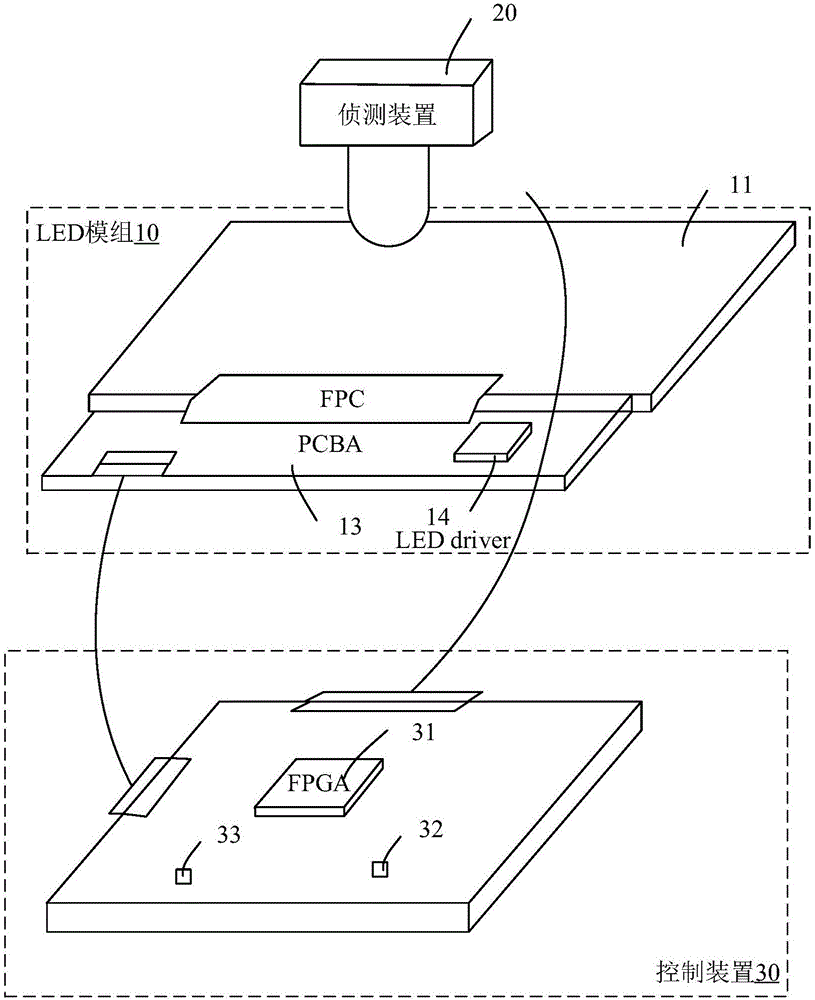
[0021] figure 1 A schematic structural diagram of a test system for an LED module according to an embodiment of the present invention is shown. Such as figure 1 As shown, the test system includes a LED module 10 to be tested, a detection device 20 and a control device 30 .

[0022] Wherein, the LED module 10 to be tested includes a display panel 11 , a flexible circuit board 12 , a PCB board 13 and an LED driving circuit 14 . Wherein, the LED driving circuit 14 provides driving current to the display panel 11 through the PCB board 13 and the flexible circuit board 1...


PUM


Abstract

The invention discloses a testing method of an LED module. The method comprises obtaining brightness of a to-be-tested LED module, adjusting a drive current of the to-be-tested LED module when the brightness of the to-be-tested LED module is not within a preset threshold interval, and repeating the above steps until the brightness of the to-be-tested LED module is whithin the preset threshold interval. According to the testing method and a system of the LED module which are provided in the invention, for an LED module brightness of which does not meet a requirement, a drive current of the LED module is adjusted to enable the brightness of the LED module to meet the requirement; and the testing method and system can be performed synchronously with EDID burned-in process in production, also can be used in big-batch operation of modules, can accurately control the brightness of the module, and can save cost.

Description

technical field [0001] The invention belongs to the field of display testing, and more specifically relates to a testing method and system for an LED module. Background technique [0002] The liquid crystal panel in the widely used liquid crystal display does not emit light, but relies on the backlight behind the liquid crystal panel to provide a light source to complete the display function. At present, the most used backlight in liquid crystal panels is light-emitting diode LED. As the backlight of liquid crystal display, LED has good color reproduction, good brightness uniformity, long service life and good shock resistance. It has been used in backlight devices of liquid crystal panels. middle. [0003] The brightness adjustment range of the brightness adjustment device of the liquid crystal module is only divided into equal parts, and can only do rough brightness output, cannot achieve precise subdivision, and cannot meet the test requirements. Such as liquid crystal ...

Claims


Application Information

Patent Timeline
Patent Type & Authority Applications(China)
IPC IPC(8): H05B33/08G02F1/13H05B44/00H05B45/12H05B45/30
CPCG02F1/1309H05B45/50
Inventor 何甲胡旭旭
Owner KUSN INFOVISION OPTOELECTRONICS
Why Eureka
Try Eureka