Corner connector for connecting at least two frame profiles of a frame which are arranged perpendicularly relative each other

A technology of corner connectors, perpendicular to each other, applied in the frame of the substation/switchgear, connecting members, connecting rods, etc., can solve problems such as access, and achieve the effect of low manufacturing

Active Publication Date: 2016-10-26
RITTALWERK RUDOLF LOH GMBH & CO KG
View PDF10 Cites 1 Cited by
  • Summary
  • Abstract
  • Description
  • Claims
  • Application Information

AI Technical Summary

Problems solved by technology

In this corner connector there is the problem that the frame rods must be manually brought into position before they can be tensioned

Method used


Image

  • Corner connector for connecting at least two frame profiles of a frame which are arranged perpendicularly relative each other
  • Corner connector for connecting at least two frame profiles of a frame which are arranged perpendicularly relative each other
  • Corner connector for connecting at least two frame profiles of a frame which are arranged perpendicularly relative each other

Examples


Embodiment Construction

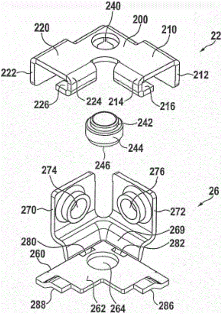
[0021] figure 1 The corner connector 20 according to the invention is shown in an exploded view. The corner connector 20 is composed of a first piece 22 , a threaded sleeve 24 and a second piece 26 . Starting from the central part 200 , the plate part 22 has two humerus parts 210 , 220 , established at an angle of 90°, the flat upper surfaces of which are aligned with the central part 200 . The respective humerus 210 , 220 is bent, wherein the bending regions 212 , 222 of the respective humerus 210 , 220 pointing away from each other protrude beyond the central part 200 at an angle of approximately 90°. The bent areas 214, 224 of the humerus 210, 220 pointing toward each other likewise protrude beyond the central part 200 at an angle of 90°, but are then bent again to form webs 216, 226, wherein the respective webs 216, 226 point oppositely. The bending areas 212, 222 are placed. In the central piece 200 there is furthermore a receiving opening 240 into which the threaded s...


PUM


Abstract

A corner connector for connecting at least two frame profiles of a frame which are arranged perpendicularly relative each other, said corner connector consisting of a plurality of parts at least one of which is designed to come to rest against one or more of the frame profiles is characterized in that the part which is designed to come to rest against one or more of the frame profiles is a first molded sheet metal part having a receiving opening in or on which a threaded sleeve is situated.

Description

technical field [0001] The invention relates to a corner connector for connecting at least two frame profiles arranged perpendicularly to each other of a rack, said corner connector comprising a plurality of parts, at least one of which is designed for leaning against Place one or more of the profiled pieces in the frame. Background technique [0002] Such a corner connector is known from DE10328408A1. In it, three mutually perpendicular frame bars should be connected to build a switchgear, especially a low-voltage switchgear. The corner connectors used for this are constructed in two parts, with the two parts each having three mutually perpendicular arms, between which the frame rods can be clamped firmly. In the corner region between the humerus are through-holes through which a screw can be threaded, which screw can only be screwed into a threaded hole on the other part when the frame rod is tensioned. In this corner connector there is the problem that the frame rods h...

Claims


Application Information

Patent Timeline
IPC IPC(8): H02B1/01F16B7/04
CPCF16B7/044H02B1/014F16B12/50F16B2012/446
Inventor T·辛德勒
Owner RITTALWERK RUDOLF LOH GMBH & CO KG
Why Eureka
Try Eureka