Fingerprint sensor and fingerprint identification method therefor

A fingerprint sensor and driver technology, applied in the sensor field, can solve problems such as unstable fingerprint entry, and achieve the effects of increasing the area of ​​fingerprint image entry, less entry information, and fast response.

Inactive Publication Date: 2016-11-02
LETV HLDG BEIJING CO LTD +1
View PDF5 Cites 5 Cited by
  • Summary
  • Abstract
  • Description
  • Claims
  • Application Information

AI Technical Summary

Problems solved by technology

[0013] This disclosure changes the traditional way of fixing the sensor and sliding the finger to the way of fixing the finger and moving the sensor, which not only has the characteristic of a large image of the sliding fingerprint sensor, but also solves the problem of unstable fingerprint entry of the sliding fingerprint sensor. Through the application The adjustment of the scene can greatly increase the area of ​​fingerprint image entry, while maintaining the characteristics of ease of use

Method used


Image

  • Fingerprint sensor and fingerprint identification method therefor
  • Fingerprint sensor and fingerprint identification method therefor
  • Fingerprint sensor and fingerprint identification method therefor

Examples


Embodiment 1

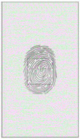
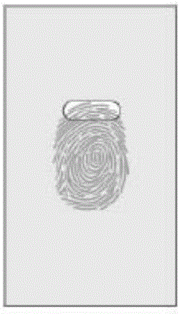
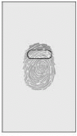
[0041] In this embodiment, the sensing module is arranged in a strip shape, and the sensing module can move linearly through the moving mechanism, such as image 3 shown. When the user performs fingerprint registration, such as Figure 4 As shown, the sensing module moves linearly from the upper end of the finger pulp to the lower end of the finger pulp through the moving mechanism to complete fingerprint entry.

[0042] The specific structure of this embodiment is as Figures 5A-5B As shown, it is a schematic diagram of a part of the structural principle of the sliding fingerprint sensor described in Embodiment 1 of the present disclosure.

[0043]In this embodiment, the base plate at the bottom is a bearing steel sheet 1a, which provides reinforcement and support for other parts of the sensor. The top is a cover plate 2a, which is buckled together with the bearing steel sheet 1a. The telescopic rod driver 3a and the telescopic rod 4a constitute a moving mechanism, and th...

Embodiment 2

[0045] In this example, if Figure 6 As shown, the sensing module is arranged in a fan shape, and the sensing module can rotate and move through the moving mechanism. When the user performs fingerprint registration, such as Figure 7 As shown, the sensing module rotates around the finger pulp through the moving mechanism, and completes fingerprint entry by rotating one circle.

[0046] The specific structure of this embodiment is as Figure 8 As shown, it is a schematic diagram of the partial structure and principle of the sliding fingerprint sensor described in the second embodiment.

[0047] In this embodiment, the base plate at the bottom is a supporting steel sheet 1b, which is used to provide reinforcement and support, a circuit board is arranged on the base plate, and the uppermost layer is a cover plate 2b, which is used to protect internal components.

[0048] The tray 3b and the rotating column 4b constitute the moving mechanism, the sensing module 5b is installed ...


PUM


Abstract

The disclosure provides a fingerprint sensor and a fingerprint identification method therefor. The fingerprint sensor comprises a substrate, a data processing module, a sensing module, a cover plate, a mobile mechanism and a control mechanism for the mobile mechanism. The data processing module and the sensing module are fixed between the substrate and the cover plate, the sensing module is electrically connected with the data processing module, the mobile mechanism is connected with the sensing module, the control mechanism is connected with the mobile mechanism, and the control mechanism controls the mobile mechanism to drive the sensing module to move in a linear or curve manner. The fingerprint identification method comprises the following steps: when finger information is detected, the sensing module is controlled to scan area of fingerprints of fingers according to a preset identification mode, the fingerprints which are input are processed, and identification information is output. The fingerprint sensor and the fingerprint identification method therefor in a technical solution of the invention can provide large images that are typical of a sliding type fingerprint sensor, and a problem of unstable fingerprint input of the sliding type fingerprint sensor can be solved.

Description

technical field [0001] The present disclosure relates to the technical field of sensors, in particular, to a fingerprint sensor and a fingerprint identification method thereof. Background technique [0002] Fingerprints are the lines formed by the uneven skin on the surface of the finger, and are composed of various ridge-shaped figures. Fingerprint features are patterns of smooth texture composed of ridges and grooves on the surface of the finger, which is highly random. Studies have shown that: fingerprint features have the characteristics of uniqueness and stability, and identity recognition can be realized accordingly. The surface area of ​​fingerprints is small and there is wear and tear, so it is difficult to obtain high-quality fingerprint images. Fingerprint sensor is a special device for obtaining fingerprint images, and plays a key role in automatic fingerprint identification systems in various industries. [0003] According to different sensor devices, fingerpr...

Claims


Application Information

Patent Timeline
IPC IPC(8): G06K9/00
CPCG06V40/13
Inventor 唐先炜
Owner LETV HLDG BEIJING CO LTD
Why Eureka
Try Eureka