Supercharge Your Innovation With Domain-Expert AI Agents!

Driving mechanism of automatic soap dispenser

A driving mechanism, soap dispenser technology, applied in the direction of electromechanical devices, electric components, control mechanical energy, etc., can solve the problems of poor reliability, easy damage, complex structure, etc., to achieve the effect of increasing torque, simple and reliable structure

Inactive Publication Date: 2016-11-09
JIANGMEN AYT ELECTRICAL APPLIANCE CO LTD
View PDF5 Cites 0 Cited by
  • Summary
  • Abstract
  • Description
  • Claims
  • Application Information

AI Technical Summary

Problems solved by technology

The automatic soap dispenser in the prior art is used to drive the liquid pump, which has a complex structure, poor reliability, and is easy to be damaged after long-term use

Method used


Image

  • Driving mechanism of automatic soap dispenser

Examples


Embodiment Construction

[0014] The present invention will be further described below in conjunction with accompanying drawing and example.

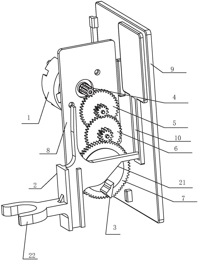
[0015] refer to figure 1 , the drive mechanism of a kind of automatic soap dispenser of the present invention, comprises motor 1, gear set, sliding support 2, control circuit, and described control circuit is connected motor to output control signal to it, and the rotating shaft of described motor 1 and The gear set is connected, and the gear set includes a plurality of transmission gears connected sequentially from top to bottom, wherein a transmission shaft 3 is arranged at the non-center of the bottom gear surface, and the transmission shaft 3 is connected with the sliding support 2 to drive The sliding support 2 moves up and down, and the sliding support 2 is fixedly connected with the pump head of the liquid outlet pump.

[0016] Described gear group comprises gear post 4, duplex gear A 5, duplex gear B 6, bull gear 7, and described gear post 4 is fixedly ...


PUM


Abstract

The invention discloses a driving mechanism of an automatic soap dispenser. The driving mechanism comprises a motor, a gear group, a slippage support and a control circuit; the control circuit is connected with the motor and is used for outputting a control signal to the motor; a rotary shaft of the motor is connected with the gear group; the gear group comprises a plurality of transmission gears which are connected in sequence from top to bottom, wherein a transmission shaft is arranged at a non-center part on the surface of the gear on the lowest side; the transmission shaft is connected with the slippage support to drive the slippage support to move up and down; the slippage support is fixedly connected with a pump head of a liquid outlet pump. The motor and the gear group drive the slippage support to compress the pump head of the liquid outlet pump, so that liquid is discharged; the gear group also has the effect of improving torque and the whole structure is simple and reliable.

Description

technical field [0001] The invention relates to a driving mechanism of an automatic soap dispenser. Background technique [0002] Soap dispenser is an electrical appliance used in hotels, restaurants, and family toilets to provide soap liquid through non-contact induction of human hands. The automatic soap dispenser in the prior art has a complex structure for driving the liquid outlet pump, has poor reliability, and is easy to be damaged after long-term use. Contents of the invention [0003] In order to overcome the deficiencies of the prior art, the object of the present invention is to provide a driving mechanism for an automatic soap dispenser that works stably and reliably. [0004] The technical scheme that the present invention adopts for solving its technical problem is: [0005] A driving mechanism for an automatic soap dispenser, including a motor, a gear set, a sliding support, and a control circuit, the control circuit is connected to the motor to output a c...

Claims


Application Information

Patent Timeline
Patent Type & Authority Applications(China)
IPC IPC(8): A47K5/12H02K7/116
CPCA47K5/12H02K7/116
Inventor 雷志威梁和瑞区棋就何宝婷
Owner JIANGMEN AYT ELECTRICAL APPLIANCE CO LTD
Features
  • R&D
  • Intellectual Property
  • Life Sciences
  • Materials
  • Tech Scout
  • Unparalleled Data Quality
  • Higher Quality Content
  • 60% Fewer Hallucinations
Learn More