Knife roller blade limiting and waste discharging device

A technology of waste discharge device and blade, which is applied in metal processing and other directions, can solve problems such as troublesome and non-removable blades, and achieve the effect of convenient waste discharge

Active Publication Date: 2016-11-09
坂崎雕刻模具(昆山)有限公司
View PDF8 Cites 0 Cited by
  • Summary
  • Abstract
  • Description
  • Claims
  • Application Information

AI Technical Summary

Problems solved by technology

[0003] The current cutter blades are often set perpendicular to the surface of the cutter roller, and the blades are not detachable. Therefore, it is troublesome to replace the cutter roller for different products

Method used


Image

  • Knife roller blade limiting and waste discharging device

Examples


Embodiment Construction

[0015] The present invention will be further described below in conjunction with the accompanying drawings and specific embodiments.

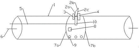
[0016] according to figure 1 , a knife roller blade limit and waste discharge device, comprising a knife roller 1, figure 1 The two ends of the middle knife roll are circular surfaces at both ends of the knife roll, and the circular surface is connected to the rotating shaft. It is characterized in that it also includes a blade that is detachably mounted on the surface of the knife roll. The blade includes the first hypotenuse 2a of the blade , blade slope top edge 2b and blade second slope 2c, blade first slope and blade second slope are arranged in parallel, and blade slope top edge connects blade first slope and blade second slope; Described blade two The ends are respectively provided with the first moving stop block 3 which moves along the extending direction parallel to the rotating shaft 6 of the knife roller, and the second moving stop...


PUM


Abstract

The invention relates to a knife roller blade limiting and waste discharging device, and belongs to the field of engraving molds. The device comprises a knife roller and is characterized by further comprising a blade detachably mounted on the surface of the knife roller, the blade comprises a first blade inclined side, an inclined blade top side and a second blade inclined side, the first blade inclined side and the second blade inclined side are arranged in parallel, and the inclined blade top side is connected with the first blade inclined side and the second blade inclined side; the two ends of the blade are provided with a first moving limiting block which moves in the extension direction parallel to the rotating axis of the knife roller and a second moving limiting block which vertically moves; the lower end of the blade is connected with a heating block; and compared with the prior art, the knife roller blade limiting and waste discharging device has the beneficial effects that the blade can be detached, blades of different sizes can be limited, through heating, the blade heats, and therefore welding is achieved, roller cutting is also achieved, and waste discharge is facilitated.

Description

technical field [0001] The invention relates to a knife roller blade limit and waste discharge device, which belongs to the field of engraving moulds. Background technique [0002] The circular die cutter roll was first used in the printing industry, especially in the cigarette package printing and packaging industry, and is a high-efficiency die-cutting tool that replaces flat pressing and punching. [0003] The current knife roll blades are often arranged perpendicular to the surface of the knife roll, and the blades are not detachable. Therefore, it is troublesome to replace the knife roll for different products. Contents of the invention [0004] In order to overcome the above-mentioned defects, the present invention provides a knife roller blade limiting and waste discharge device with detachable blades, positioning of blades of different sizes, heating of the blades to realize welding, and convenient waste discharge. [0005] In order to solve the above-mentioned te...

Claims


Application Information

Patent Timeline
IPC IPC(8): B26F1/44B26D7/26B26D7/27B26D7/18
CPCB26D7/1845B26D7/2614B26D7/27B26F1/44B26F2001/4463
Inventor 陈良
Owner 坂崎雕刻模具(昆山)有限公司
Why Eureka
Try Eureka