Eureka AIR delivers breakthrough ideas for toughest innovation challenges, trusted by R&D personnel around the world.

Side sealing mechanism of film packaging machine

A packaging machine and film technology, applied in the directions of packaging sealing/fastening, packaging, transportation packaging, etc., can solve the problems of damaged packaging bags, easy to stick knives, unable to seal, etc., to achieve beautiful appearance, fast heating and stability , strong sealing effect

Inactive Publication Date: 2016-11-09
平阳安博机械设备厂
View PDF9 Cites 2 Cited by
  • Summary
  • Abstract
  • Description
  • Claims
  • Application Information

AI Technical Summary

Problems solved by technology

[0002] The side sealing of existing film packaging machines mainly adopts two methods, one is to use rollers to directly roll heat seal, and the other is to use a heat-sealing plate for heat-sealing. The tube is heated by a heating tube. The above two solutions can only be used for heat sealing of thicker films, and are not suitable for thin films such as PE and CPP. The main reason is that when the heat sealing temperature is high, sticking is easy Knife phenomenon, that is, the film sticks to the roller or the heat-sealing plate, resulting in damage to the packaging bag. If the temperature is low, the adhesion cannot be achieved, that is, the seal cannot be achieved
Therefore, the existing film packaging machine cannot realize the packaging of thin films such as PE and CPP.

Method used


Image

  • Side sealing mechanism of film packaging machine
  • Side sealing mechanism of film packaging machine

Examples


Embodiment Construction

[0014] The working principle and relevant details of the present invention will be further described below in conjunction with the accompanying drawings.

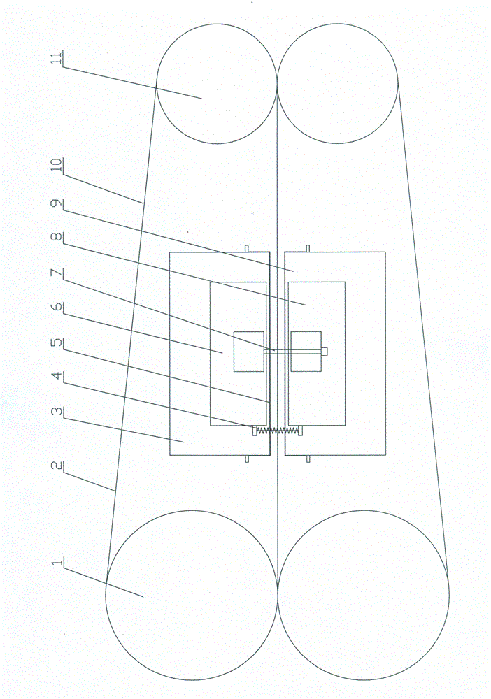
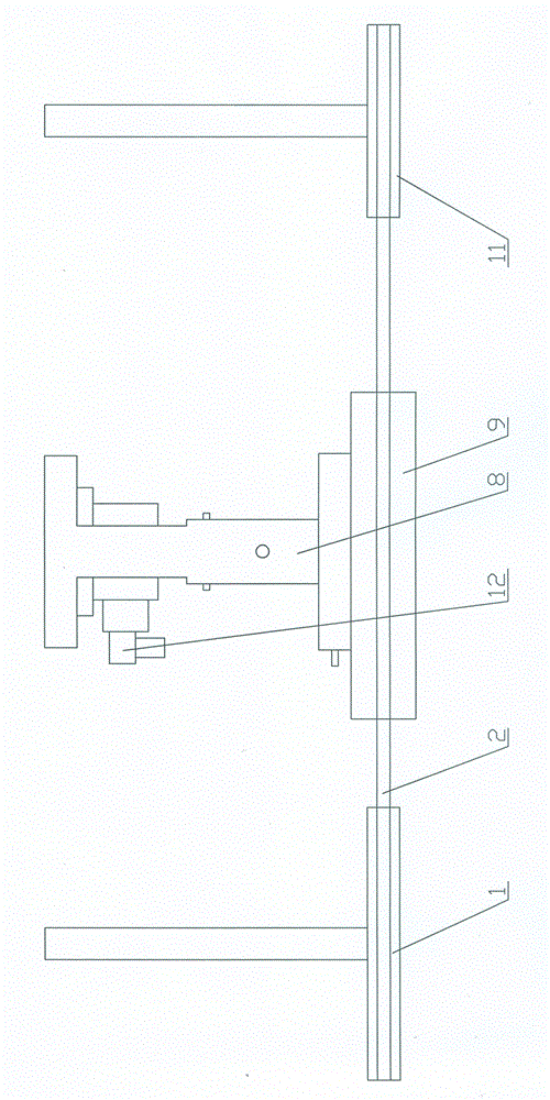
[0015] Referring to the accompanying drawings, the side sealing mechanism of this kind of film packaging machine includes a frame and a heat-sealing device and a traction device installed on the frame. The heat-sealing device includes left and right heat-sealing plates 3 and right Heat-sealing plate 9, heating wire 5 is arranged on the heat-sealing plate of the left heat-sealing plate 3 and the right heat-sealing plate 9, and the heating wire 5 described in this embodiment is installed on the left and right heat-sealing plates 3, 9 on. The traction device includes two groups of transmission parts symmetrically arranged left and right. The transmission parts include a front transmission wheel 1, a rear transmission wheel 11 and a heat-insulating transmission belt 2. The front transmission wheel 1 and the rear transmission wh...


PUM


Abstract

The invention discloses a side sealing mechanism of a film packaging machine. The side sealing mechanism comprises a rack, a heat sealing device and a traction device, wherein the heat sealing device and the traction device are mounted on the rack. The heat sealing device comprises a left heat sealing plate and a right heat sealing plate which are arranged in bilateral symmetry. The traction device comprises two sets of transmission components arranged in bilateral symmetry. The side sealing mechanism is characterized in that each transmission component comprises a front transmission wheel, a rear transmission wheel and a heat isolation transmission belt; the heat sealing device is arranged between the front transmission wheels and the rear transmission wheels; and each heat isolation transmission belt penetrates a clearance between the left heat sealing plate and the right heat sealing plate and is arranged on the corresponding front transmission wheel and rear transmission wheel. According to the side sealing mechanism, heat of the left heat sealing plate and the right heat sealing plate is stably transmitted to a film through the heat isolation transmission belts, and therefore the film is prevented from being damaged by the high temperature; and the film is prevented from being bonded to the left heat sealing plate and the right heat sealing plate during heat sealing, and therefore it is guaranteed that the film is intact.

Description

technical field [0001] The invention relates to an improved invention of a film packaging machine, in particular to a side sealing mechanism of the film packaging machine. Background technique [0002] The side sealing of existing film packaging machines mainly adopts two methods, one is to use rollers to directly roll heat seal, and the other is to use a heat-sealing plate for heat-sealing. The tube is heated by a heating tube. The above two solutions can only be used for heat sealing of thicker films, and are not suitable for thin films such as PE and CPP. The main reason is that when the heat sealing temperature is high, sticking is easy Knife phenomenon, that is, the film sticks to the roller or the heat-sealing plate, resulting in damage to the packaging bag. If the temperature is low, the adhesion cannot be achieved, that is, the seal cannot be achieved. Therefore, the existing film packaging machine cannot realize the packaging of thin films such as PE and CPP. Con...

Claims


Application Information

Patent Timeline
IPC IPC(8): B65B51/26
CPCB65B51/26
Inventor 王照沛林形安曹振学阮棉云
Owner 平阳安博机械设备厂
Why Eureka
Eureka Blog
Learn More