
A hydraulic system with good sealing performance and reduced leakage

A sealing performance and hydraulic system technology, which is applied in the direction of fluid pressure actuation system components, fluid pressure actuation devices, servo motors, etc., to achieve good control of the hydraulic system, improve oil leakage, and optimize the effect of the cylinder

Inactive Publication Date: 2018-01-30
成都翼高九天科技有限公司
View PDF6 Cites 0 Cited by
  • Summary
  • Abstract
  • Description
  • Claims
  • Application Information

AI Technical Summary

Problems solved by technology

[0004] The technical problem to be solved by the present invention is to cool down the hydraulic system and reduce oil leakage. The purpose is to provide a workpiece positioning and clamping device to solve the problems of cooling down the hydraulic system and reducing oil leakage.

Method used


Image

  • A hydraulic system with good sealing performance and reduced leakage
  • A hydraulic system with good sealing performance and reduced leakage

Examples


Embodiment

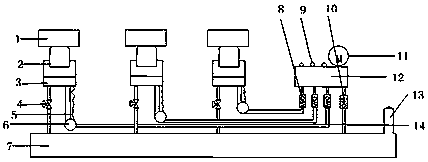
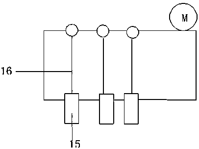
[0021] Such as figure 1 As shown, a hydraulic system with good sealing performance and reduced leakage in the present invention includes a main hydraulic cylinder 12 and a connected motor 11, and three push switches 9 drive three connecting shafts 16 to control three oil pipe interfaces 15. The sub-hydraulic cylinder 3, the oil pipe 14, the diameter of the oil pipe is 10CM, the oil tank 7 and the pump head 2 inside the sub-hydraulic cylinder 3, the pump head 2 supports the heavy object 1, and the oil pipe 14 connecting the main hydraulic cylinder 12 and the sub-hydraulic cylinder 3 is set An oil outlet check valve 8, an oil suction check valve 10 is arranged on the oil pipe 14 connecting the main hydraulic cylinder 12 and the fuel tank 7, a cut-off valve 4 is set on the oil pipe 14 connecting the sub-hydraulic cylinder 3 and the fuel tank 7 and the cut-off valve 4 and the oil tank 7 A pressure gauge is connected between them, a cavity 6 and an air-permeable layer 5 are set on ...


PUM


Abstract

The invention discloses a hydraulic system good in seal performance and capable of reducing leakage. The hydraulic system good in seal performance and capable of reducing leakage comprises a main hydraulic cylinder, branch hydraulic cylinders, oil pipes, an oil tank and pump heads in the branch hydraulic cylinders. An oil outlet one-way valve is arranged on each oil pipe connected with the main hydraulic cylinder and the corresponding branch hydraulic cylinder. Each oil outlet one-way valve corresponds to one press switch. An oil suction one-way valve is arranged on the oil pipe connected with the main hydraulic cylinder and the oil tank. The oil pipes connected with the branch hydraulic cylinders and the oil tank are each provided with a check valve. The hydraulic system good in seal performance and capable of reducing leakage is characterized in that the oil pipes connected with the main hydraulic cylinder and the branch hydraulic cylinders are each provided with a cavity and a ventilation layer, and each cavity is arranged at the position where hydraulic oil is conveyed from a low portion to a high portion; each ventilation layer is a cylindrical sleeve outside the corresponding oil pipe, one end of each ventilation layer is opened, the other end of each ventilation layer is connected with the corresponding cavity, the inner portion of each ventilation layer and the surface of the corresponding oil pipe form a cavity layer, and the surface of each ventilation layer is provided with nine small holes; a vent hole is formed in the outer portion of the oil tank; and the bottom of the main hydraulic cylinder is connected with three oil pipe connectors, the upper portion of the main hydraulic cylinder is connected with the three press switches, and three connecting shafts are arranged in the main hydraulic cylinder and enable the oil pipe connectors and the press switches to be connected.

Description

technical field [0001] The invention relates to a hydraulic system with good sealing performance, in particular to a hydraulic system with good sealing performance and reduced leakage. Background technique [0002] In 1795, Joseph Braman of England used water as a working medium in London and applied it to industry in the form of a hydraulic press, giving birth to the world's first hydraulic press. In 1905, the working medium was changed from water to oil, which was further improved. After the First World War, hydraulic transmission was widely used, especially after 1920, it developed more rapidly. Hydraulic components only began to enter the formal industrial production stage during the 20 years at the end of the 19th century and the beginning of the 20th century. In 1925, Vickers invented the pressure balanced vane pump, which laid the foundation for the gradual establishment of the modern hydraulic component industry or hydraulic transmission. Konstantin Niske's theore...

Claims


Application Information

Patent Timeline
Patent Type & Authority Patents(China)
IPC IPC(8): F15B11/17F15B21/04
CPCF15B11/17F15B21/042F15B2211/205
Inventor 于喜龙
Owner 成都翼高九天科技有限公司
Learn More