Novel range hood

A range hood, a new type of technology, applied in the direction of removing oil fume, household heating, lighting and heating equipment, etc., can solve the problems of splashing oil and water, unable to collect and gather smoke, escape, etc., and achieve the effect of good smoke exhaust effect.

Inactive Publication Date: 2016-11-09
杨德红
View PDF6 Cites 8 Cited by
  • Summary
  • Abstract
  • Description
  • Claims
  • Application Information

AI Technical Summary

Problems solved by technology

[0002] The range hood used in existing households sucks the oil fume from the center of the lower bottom of the air guide cover, and the oil fume is usually sucked from the center from the bottom up. The smoke exhaust pipe is pulled out of the range hood, but when the range hood is used, it cannot effectively collect and gather the smoke, resulting in the diffusion and escape of the smoke, and the user often encounters high-temperature oil smoke and oil-water splashes during use. question

Method used


Image

  • Novel range hood
  • Novel range hood
  • Novel range hood

Examples


Embodiment 1

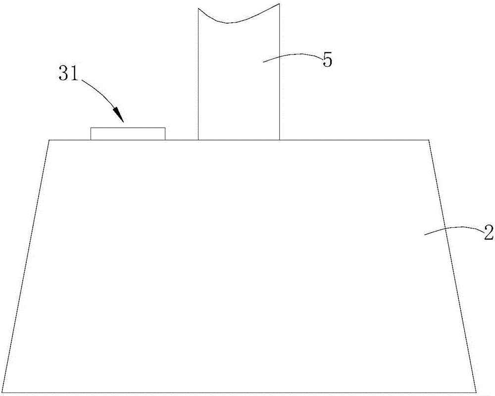
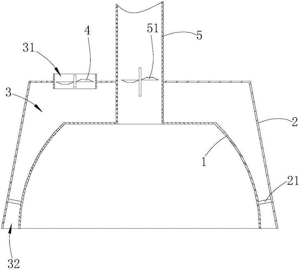
[0014] Such as Figures 1 to 3 shown

[0015] The novel range hood comprises a guide cover 1 , a smoke exhauster 51 , a smoke exhaust pipe 5 , an outer casing 2 and an air intake fan 4 .

[0016] The shroud 1 is roughly in the shape of an inverted funnel, the opening of the shroud 1 is downward, the outer shell 2 is arranged outside the shroud 1, and the outer shell 2 and the shroud 1 are fixed by several connecting columns 21, and the guide The space between the flow cover 1 and the outer casing 2 forms a distribution chamber 3, and the rear end surface of the outer casing 2 is provided with an air inlet 31 communicating with the outside, and the air inlet 4 is arranged at the air inlet 31, and the lower side of the outer casing 2 is connected to the air guide There is a gap between the front side, left side and right side of the cover 1, and the gap forms a concave air outlet 32 ​​on the lower end surface of the distribution cavity 3, and the air outlet 32 ​​is distributed ...

Embodiment 2

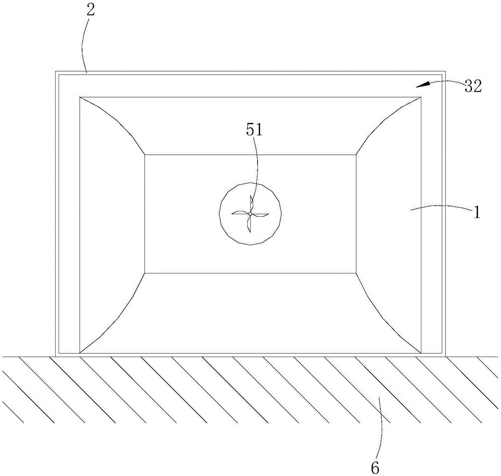
[0022] Such as Figure 4 shown

[0023] The difference between this embodiment and Embodiment 1 is that there are gaps between the lower side of the outer casing 2a and the front side, rear side, left side and right side of the shroud 1a, and the gap forms a square ring on the lower end surface of the shunt cavity. The air outlet 32a, when the novel range hood of this embodiment is installed on the top of the wall, when the side wall of the housing is not in contact with the wall, the annular air outlet 32a can form an air curtain to the four sides of the oil fume source.

[0024] In addition, if the side wall of the new range hood of this embodiment is installed on the wall 6a, a baffle 7a can be set to cover any side of the annular air outlet 32a, so that the original square annular air outlet becomes concave. tuyere.


PUM


Abstract

The invention provides a novel range hood. The novel range hood comprises a flow guide cover, a smoke exhauster and a smoke exhaust pipe, wherein an opening of the flow guide cover is aligned to an oil smoke source, the smoke exhaust pipe communicates with the top of the flow guide cover and the exterior of the novel range hood, and the smoke exhauster guides air inside the flow guide cover out of the novel range hood through the smoke exhaust pipe; a flow separation cavity and an air inlet fan are arranged outside the flow guide cover, an air inlet communicating with the exterior is formed in a wall of the flow separation cavity, the flow separation cavity is provided with an air outlet, and the air inlet fan blows the air to the periphery of the oil smoke source through the air outlet of the flow separation cavity, so that an air curtain is formed. The air in the flow separation cavity is exhausted through the air outlet and then is blown to the periphery of the oil smoke source, the air curtain is formed around the oil smoke source, diffusion or escape of the smoke is prevented, and the smoke is forced to be gathered towards the middle and can be conveniently exhausted out of the novel range hood by the smoke exhauster.

Description

technical field [0001] The invention relates to a range hood. Background technique [0002] The range hood used in existing households sucks the oil fume from the center of the lower bottom of the air guide cover, and the oil fume is usually sucked from the center from the bottom up. The smoke exhaust pipe is pulled out of the range hood, but when the range hood is used, it cannot effectively collect and gather the smoke, resulting in the diffusion and escape of the smoke, and the user often encounters high-temperature oil smoke and oil-water splashes during use. question. Contents of the invention [0003] The technical problem to be solved by the present invention is to provide a novel range hood with simple structure and effective control of the diffusion of oil fume. [0004] In order to solve the above-mentioned technical problems, the present invention provides a novel range hood, which includes a deflector, a smoke exhaust machine and a smoke exhaust pipe. Outsid...

Claims


Application Information

Patent Timeline
Patent Type & Authority Applications(China)
IPC IPC(8): F24C15/20
CPCF24C15/2028
Inventor 杨德红杨洋王松李传奇
Owner 杨德红
Why Eureka
Try Eureka