Focusing assembly for track lamp and track lamp using focusing assembly

A track light and focusing technology, which is applied to semiconductor devices of light-emitting elements, parts of lighting devices, cooling/heating devices of lighting devices, etc. Assembly effect

Pending Publication Date: 2020-02-04
CHANGZHOU DOL LED PHOTOELECTRICITY
View PDF1 Cites 1 Cited by
  • Summary
  • Abstract
  • Description
  • Claims
  • Application Information

AI Technical Summary

Problems solved by technology

[0002] Track light is a light installed on a similar track, and the irradiation angle can be adjusted arbitrarily. It is generally used as a spotlight in places that require key lighting. It is also called track spotlights, track lights, etc. It mainly uses COB light sources and has light effects. High, uniform light output, no glare, energy saving and environmental protection, it is the preferred equipment in lighting equipment; the existing track light, in the patent document with the authorized announcement number CN208011429U and the name of a focus-adjustable track light, records a A fixed ring fixed on the outer end of the lamp, a focus ring fixed on the outer end of the fixed ring and rotatable relative to the fixed ring, and surrounded by the focus ring and the fixed ring The focus assembly composed of the rotating face ring in the space and the focusing lens arranged in the rotating face ring, when the focus ring is rotated, the first internal thread and the first external thread act on the rotating face ring along the axial direction Move back and forth, thereby driving the focusing lens to move forward and backward along the axial direction, thereby changing the distance between the focusing lens and the light source, adjusting the light angle of the light source, and playing the role of focusing. After the focusing assembly of the above structure rotates, it extends out of the front end of the lamp body ,Affect the appearance

Method used


Image

  • Focusing assembly for track lamp and track lamp using focusing assembly
  • Focusing assembly for track lamp and track lamp using focusing assembly
  • Focusing assembly for track lamp and track lamp using focusing assembly

Examples


Embodiment 1

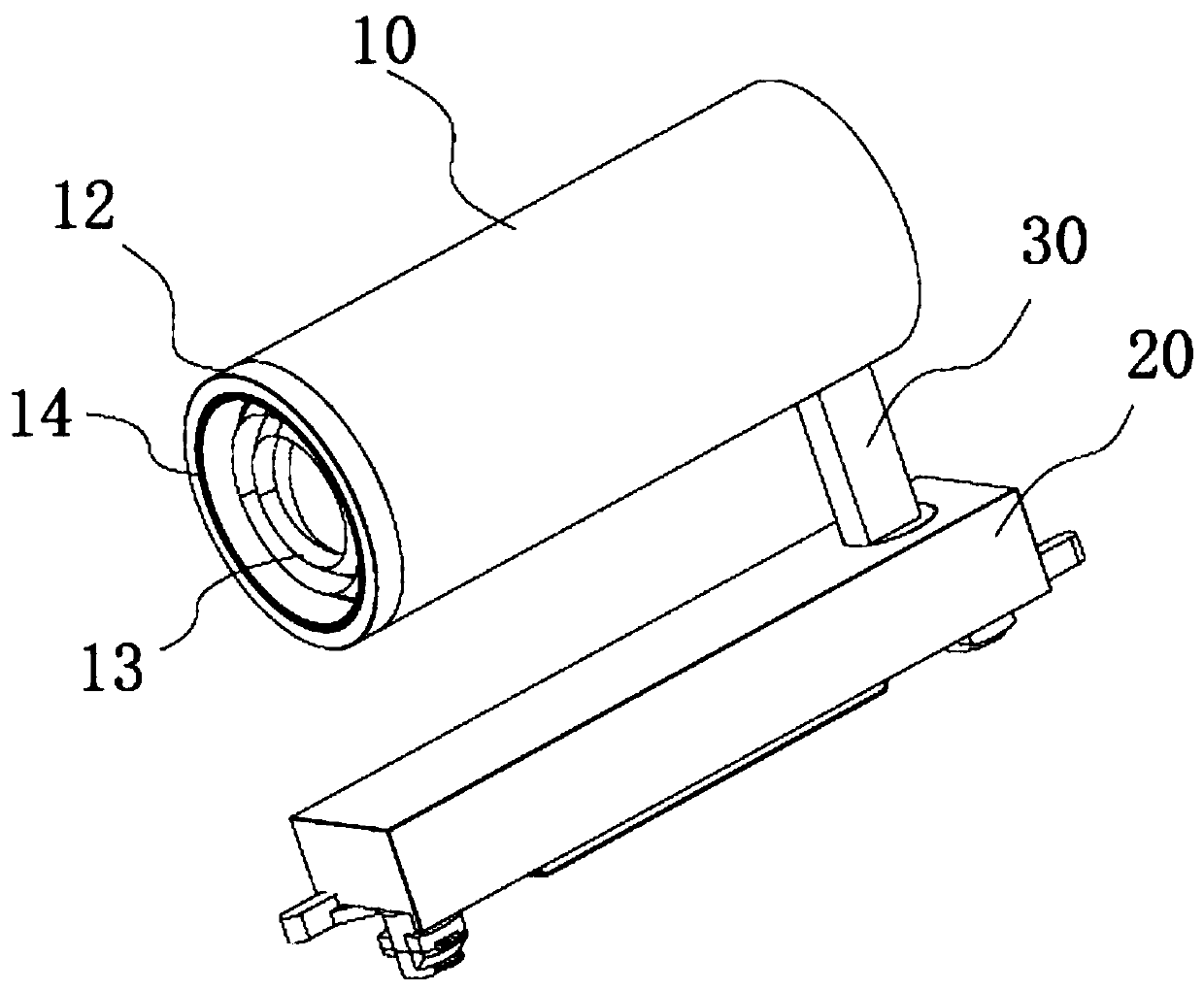
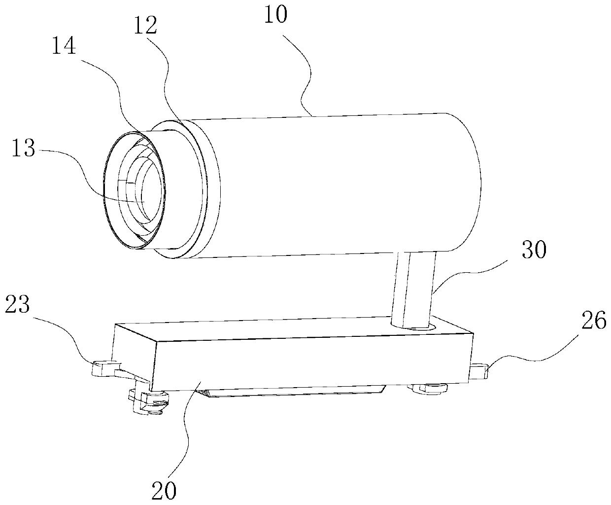
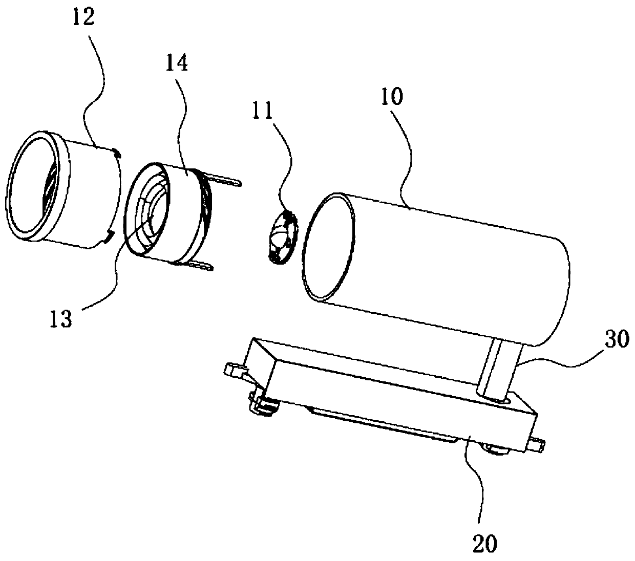
[0041] Such as figure 1 with image 3 As shown, the focusing assembly for track lights of this embodiment includes a coaxially arranged lamp tube 10, a light source, a condenser 11, a zoom lens 13, and a rotating sleeve 12 and a translation sleeve 14, and a condenser 11 Consists of an integrally formed concave-convex lens 111 and a disc 112, such as Figure 4 with Picture 10 The lamp tube 10 shown includes a lamp tube body 101 and a lamp tube rear cover. A heat dissipation base 102 is provided in the middle of the lamp tube body 101. The heat dissipation base 102 includes an integrally formed base center column and a plurality of heat dissipation fins 104. , The heat dissipation fins 104 are arranged radially outwardly along the center post of the base, one end of each heat dissipation fin 104 is connected with the center post of the base, and the other end is connected with the inner wall of the lamp tube body 101.

[0042] A light source, a meniscus lens 111, and a zoom lens 13...

Embodiment 2

[0054] On the basis of embodiment 1, the focusing assembly for track lights of this embodiment has the following deformations:

[0055] Such as Figure 13 As shown, the front end of the rotating sleeve 12 is no longer provided with a scale ring 124, or a scale value is directly set on the end surface of the front end of the rotating sleeve 12. The rotating sleeve 12 is placed in the lamp tube 10 during assembly, and the front end of the rotating sleeve 12 It is arranged flush with the front end of the lamp tube 10, or the front end of the rotating sleeve 12 is slightly lower than the front end of the lamp tube 10 so that the rotating sleeve 12 is completely placed in the lamp tube 10, and the front end of the rotating sleeve 12 is away from the lamp tube The front end of 10 should not be too far away, subject to the user’s finger touch. An internal thread is provided on the inner wall of the front end of the rotating sleeve body. The translation sleeve 14 includes a translation sl...

Embodiment 3

[0057] On the basis of Embodiment 2, the focusing assembly for track lights of this embodiment has the following deformations:

[0058] The zoomable track light also includes a honeycomb panel 50 adapted to the translation sleeve 14, such as Figure 14 with Figure 15 As shown, the honeycomb plate 50 is a circular thin plate whose diameter is adapted to the inner diameter of the translation sleeve 14, so that the honeycomb plate 50 can be fixedly arranged in the translation sleeve 14, and the translation sleeve 14 and the rotation sleeve 12 are placed In the lamp tube 10, and the honeycomb panel 50 is arranged in front of the zoom lens 13, while not affecting the light transmission, it can prevent the light projected by the zoom lens 13 from generating glare and realize the anti-glare function.


PUM


Abstract

The invention relates to a focusing assembly for a track lamp and the track lamp using the focusing assembly. The focusing assembly for the track lamp comprises a lamp barrel, a light source, a concave-convex lens and a zoom lens which are coaxially arranged, the concave-convex lens is fixedly arranged in the lamp barrel, the light source is fixedly arranged on the concave side of the concave-convex lens, the focusing assembly further comprises a rotating sleeve and a translation sleeve, the translation sleeve is in threaded fit with the rotating sleeve, a limiting insertion strip of the translation sleeve is arranged in an insertion strip slide way, so that when the rotating sleeve is rotated, the rotating sleeve can be driven to rotate in the lamp barrel, and the translation sleeve is driven by the rotating sleeve to axially translate along the lamp barrel, so that the axial distance between the zoom lens and the concave-convex lens is adjusted.

Description

Technical field [0001] The invention relates to the technical field of lighting auxiliary equipment, in particular to a focusing assembly for track lights and a track light using the focusing assembly. Background technique [0002] A track light is a light installed on a similar track, which can adjust the angle of illumination at will. It is generally used as a spotlight in places that require key lighting. It is also called track spotlights, track lights, etc., mainly using COB light sources, with light effects The characteristics of high, uniform light, no glare, energy saving and environmental protection, are the preferred equipment in the lighting equipment; the existing track light, in the patent document with the authorized announcement number CN208011429U and the name of a focusing track light, records a This is composed of a fixed ring fixed at the end of the lamp body, a focusing ring fixed at the outer end of the fixed ring and rotatable relative to the fixed ring, arr...

Claims


Application Information

Patent Timeline
Patent Type & Authority Applications(China)
IPC IPC(8): F21S8/00F21V5/04F21V14/06F21V17/16F21V19/00F21V29/83F21V29/77F21Y115/10
CPCF21S8/00F21V5/04F21V14/06F21V17/164F21V19/0015F21V29/77F21V29/83F21Y2115/10
Inventor 涂利敏
Owner CHANGZHOU DOL LED PHOTOELECTRICITY
Why Eureka
Try Eureka