Unlock instant, AI-driven research and patent intelligence for your innovation.
Deep hole groove measurement device and usage method
What is Al technical title?
Al technical title is built by PatSnap Al team. It summarizes the technical point description of the patent document.
A measuring device and groove technology, applied in the direction of measuring devices, mechanical measuring devices, mechanical devices, etc., can solve the problems of limited jaw length, limited measurement depth, and inability to measure deep holes, and achieve the effect of solving difficult measurement
Inactive Publication Date: 2016-11-09
中国人民解放军第五七〇六工厂
View PDF9 Cites 0 Cited by
Summary
Abstract
Description
Claims
Application Information
AI Technical Summary
This helps you quickly interpret patents by identifying the three key elements:
Problems solved by technology
Method used
Benefits of technology
Problems solved by technology
[0002] In the field of mechanical manufacturing, internal groove calipers are usually used to measure the inner groove of parts. However, due to the limited length of the jaws of the internal groove caliper, the depth that can be measured is limited. It is generally impossible to measure deep holes with a depth of more than 100mm.
In addition, the measurement accuracy of the inner groove caliper is generally 0.02mm. For the inner hole groove whose measurement accuracy is higher than 0.02mm, the inner groove caliper cannot meet the requirements.
Method used
Image
Click on the blue label to locate the original text in one second.
Reading with bidirectional positioning of images and text.
Examples
Embodiment 1
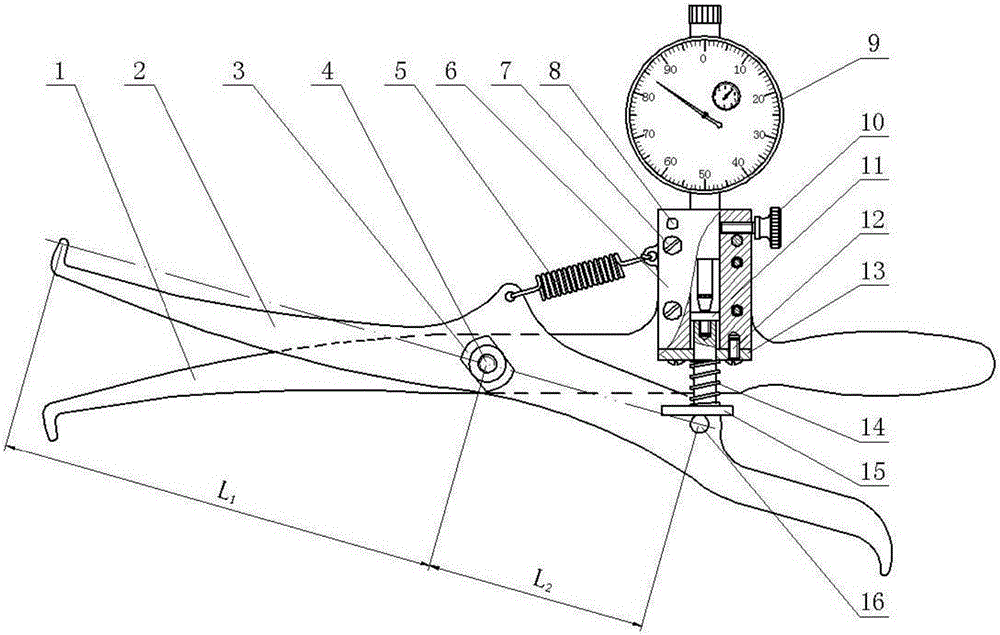
[0017] Embodiment 1, referring to accompanying drawing, a kind of deep hole groove measuring device, it comprises: lower jaw 1, upper jaw 2, flat nut 3, flat head screw 4, extension spring 5, support block 6, sink Head screw 7, cylindrical pin 8, dial indicator 9, knurled screw 10, top cap 11, round head screw 12, baffle plate 13, compression spring 14, ejector rod 15, pin shaft 16;
[0018] After the upper jaw 2 and the lower jaw 1 intersect, they are connected together with the flat nut 3 through the flat head screw 4 in the middle, forming a scissors structure with one end as the handle end and the other end as the working end. The upper jaw 2 and the lower jaw The claw 1 can rotate around the flat head screw 4;
[0019] The working end of the upper jaw 2 is bent outward to form a tip, and the handle end is provided with a pin shaft 16; the distance between the tip axis and the connection point of the upper jaw 2 and the lower jaw 1 is L1, and the connection point and the p...
Embodiment 2
[0024] Embodiment 2, a kind of deep hole groove measuring device using method, it uses the deep hole groove measuring device as described in embodiment 1, and comprises the following steps:
[0025] A. Use the outer diametermicrometer to calibrate the deep hole groove measuring device, and rotate the dial of the dial indicator 9 so that the pointer is aligned with the "0" position;
[0026] B. Hold the handle end of the upper jaw 2 and the lower jaw 1 tightly, close the working ends of the upper jaw 2 and the lower jaw 1, and then extend the working end into the inner hole of the part to be tested, so that the upper jaw 2, The tip of the lower jaw 1 is respectively aligned with the two ends of the inner hole groove of the part to be tested;
[0027] C. Read the value of the dial indicator 9, multiply the value by 2, which is the size value of the inner hole groove of the part to be tested;
[0028] D. After the measurement is completed, hold the handle ends of the upper jaw ...
PUM
Abstract
The invention belongs to a machinery dimension measurement tool, and particularly relates to the measurement of sizes of the deep hole groove members. The invention discloses a deep hole groove measurement device. The deep hole groove measurement device is characterized in that: a support block (6) is arranged on the front side of a rear end handle of a lower clamping claw (1) and is fixed on the lower clamping claw (1) through a sunk screw (7) and a cylindrical pin (8); an indicating gauge (9) is inserted into the support block (6) and is fastened through a knurled screw (10); the contact of the indicating gauge (9) is in contact with an ejector cap (11); a compression spring (14) sleeves a propping rod (15) which is in screw connection with the ejector cap (11); the compression spring (14) is abutted between a blocking plate (13) which is fixed on the lower end of the support block (6) by a half-round head screw (12) and a rectangle bottom of the ejector rod (15); and under the action of the compression spring (14), the rectangle bottom of the ejector rod (15) is pressed on a pin roll (16). By virtue of the indicating gauge, the deep hole groove measurement device and the usage method can perform accuracy measurement on the deep hole groove kind members so as to solve a difficulty that the deep hole groove is not easy to measure.
Description
technical field [0001] The invention belongs to a mechanical size measuring instrument, in particular to the measurement of the size of deep hole groove parts. Background technique [0002] In the field of mechanical manufacturing, internal groove calipers are usually used to measure the inner groove of parts. However, due to the limited length of the jaws of the internal groove caliper, the depth that can be measured is limited. It is generally impossible to measure deep holes with a depth of more than 100mm. In addition, the measurement accuracy of the inner groove caliper is generally 0.02mm. For the inner hole groove whose measurement accuracy is higher than 0.02mm, the inner groove caliper cannot meet the requirements. Contents of the invention [0003] The object of the present invention is to provide a device for measuring deep hole grooves to realize accurate measurement of the dimensions of deep hole groove parts. [0004] The technical solution of the present in...
Claims
Application Information
Patent Timeline
Application Date:The date an application was filed.
Publication Date:The date a patent or application was officially published.
First Publication Date:The earliest publication date of a patent with the same application number.
Issue Date:Publication date of the patent grant document.
PCT Entry Date:The Entry date of PCT National Phase.
Estimated Expiry Date:The statutory expiry date of a patent right according to the Patent Law, and it is the longest term of protection that the patent right can achieve without the termination of the patent right due to other reasons(Term extension factor has been taken into account ).
Invalid Date:Actual expiry date is based on effective date or publication date of legal transaction data of invalid patent.

