
Gear fault diagnosis method based on ESMF and energy operator demodulation

An energy operator demodulation and fault diagnosis technology, applied in the testing of machine gear/transmission mechanism, measuring device, testing of mechanical components, etc. frequency and other issues, to achieve the effect of good demodulation effect and small calculation amount

Inactive Publication Date: 2016-11-09
UNIV OF ELECTRONIC SCI & TECH OF CHINA
View PDF5 Cites 9 Cited by
  • Summary
  • Abstract
  • Description
  • Claims
  • Application Information

AI Technical Summary

Problems solved by technology

[0005] The purpose of the present invention is to solve the phenomenon of envelope overfitting and underfitting, endpoint effect, and modal confusion in the adaptive decomposition method for non-stationary signals in the prior art, and the use of Hilbert transform demodulation method The error is large when demodulating single-component AM-FM signals, and unexplainable negative frequencies often appear in the demodulation process. A gear fault diagnosis method based on ESMD and energy operator demodulation is proposed

Method used


Image

  • Gear fault diagnosis method based on ESMF and energy operator demodulation
  • Gear fault diagnosis method based on ESMF and energy operator demodulation
  • Gear fault diagnosis method based on ESMF and energy operator demodulation

Examples


Embodiment 1

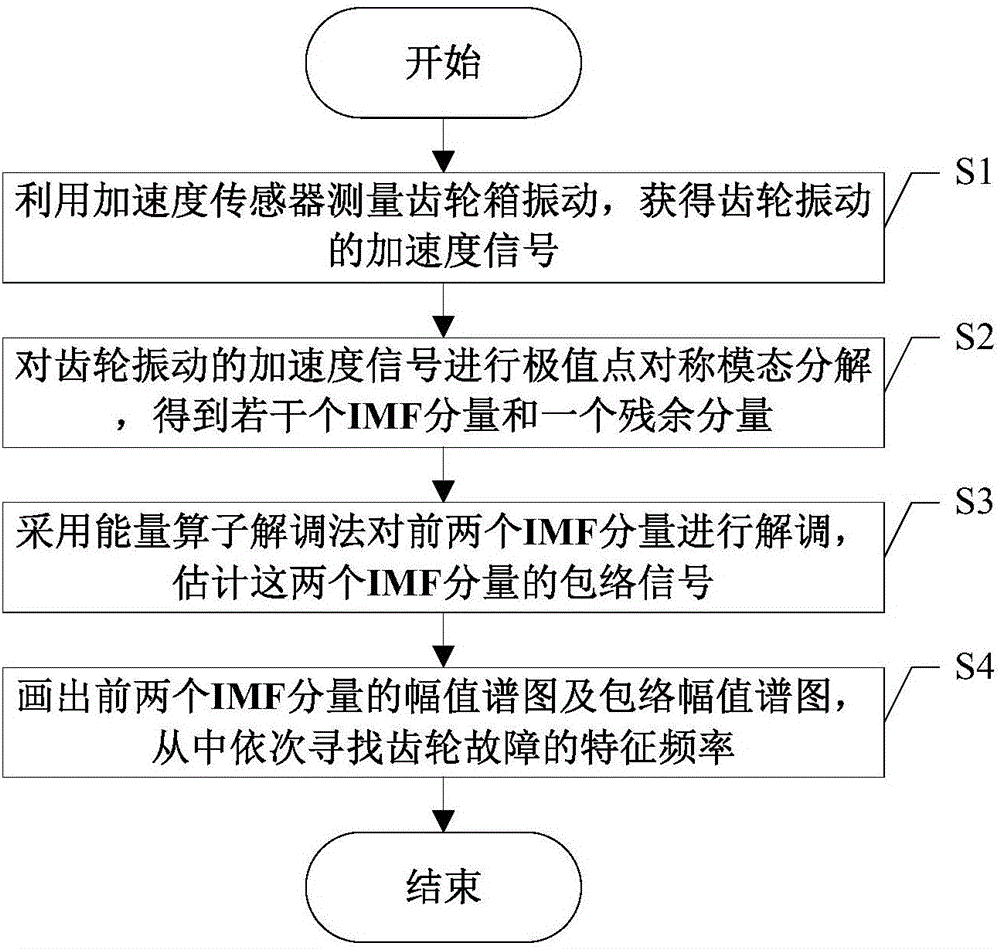
[0076] S1. Using an acceleration sensor to measure the vibration of the gear box to obtain an acceleration signal of the gear vibration.

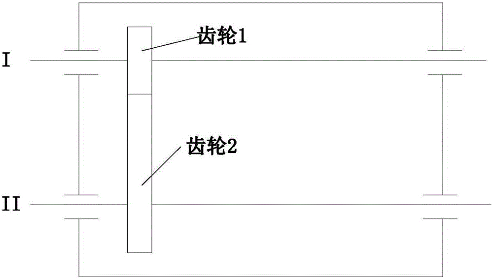
[0077] Build an experimental device for simulating gear faults. The schematic diagram of the gear box structure is shown in image 3 As shown, gear 1 is the driving gear, and gear 2 is the driven gear. One tooth of gear 2 is artificially cut, and gear 1 is normal, so as to simulate a gear broken tooth fault. gear 1 tooth number z 1 =55, gear 2 tooth number z 2 =75, modulus m=2, install the acceleration sensor on the gear box body, collect the gear vibration signal, the sampling frequency is 3600Hz, the sampling time is 1 second, and the output shaft (axis II) rotates at a speed of 820r / min The next step is to collect a group of vibration signals under the condition of broken teeth of gears. The collected vibration acceleration signal in the case of gear failure is x p (t), such as Figure 4 shown.

[0078] From the known conditions ab...

Embodiment 2

[0094] S1. Using an acceleration sensor to measure the vibration of the gear box to obtain an acceleration signal of the gear vibration.

[0095] Replace the gear 2 with the same normal gear, and the rest of the parameter settings are the same as in the first embodiment, and the vibration acceleration signal of the measured gear under normal conditions is x q (t), such as Figure 8 shown.

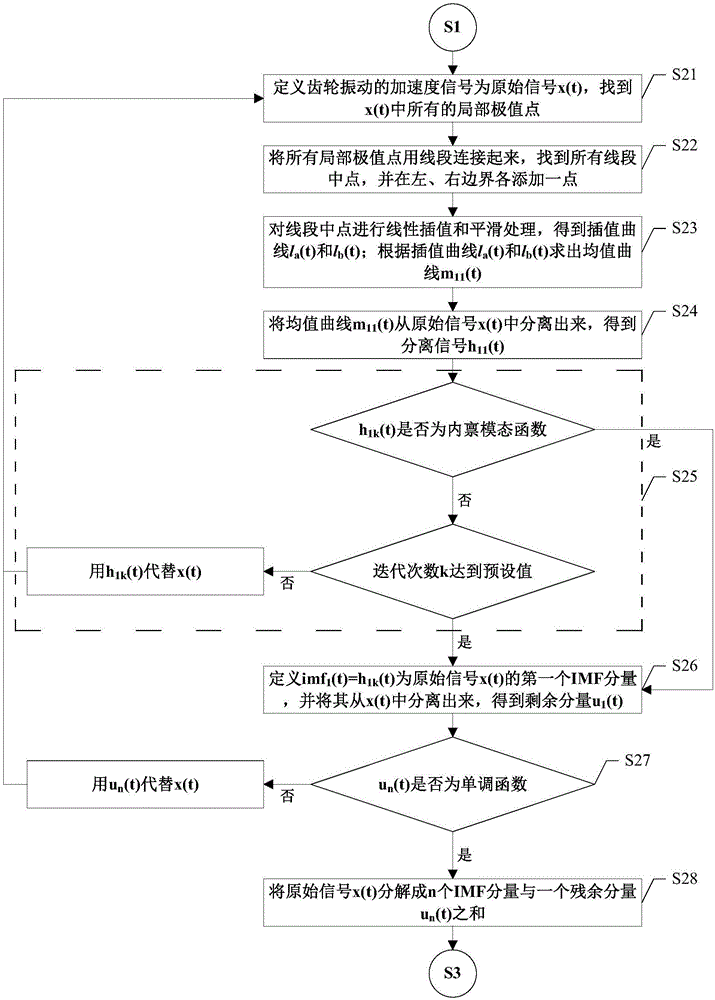
[0096] S2. Perform extremum point symmetric mode decomposition on the acceleration signal of gear vibration to obtain several IMF components and a residual component.

[0097] For vibration signal x q (t) Carry out extreme point symmetric mode decomposition to obtain 4 IMF components, denoted as (c 1 (t),c 2 (t),c 3 (t),c 4 (t)), and a residual component, denoted as r 4 (t).

[0098] S3, using the energy operator demodulation method to the first two IMF components c 1 (t), c 2 (t) Demodulate and estimate the envelope signals of the two IMF components.

[0099] S4. Draw the amplit...


PUM


Abstract

The invention discloses a gear fault diagnosis method based on ESMF and energy operator demodulation. The gear fault diagnosis method comprises steps of adopting an extreme point symmetric mode decomposition method to realize adaptive decomposition on a vibration signal of a gear fault, wherein first two IMF components comprise rich information of the gear fault in a decomposition result, envelope line over fitting and under fitting phenomenon are overcome, an end effect is weak and operation time is less; performing energy operator demodulation on the first two IMF components to obtain an envelope signal, wherein the demodulation effect is good and calculation is less; and successively searching frequency corresponding to the gear fault from amplitude spectrums and envelope amplitude spectrums of the first IMF component and the second IMF component so as to realize gear fault diagnosis.

Description

technical field [0001] The invention belongs to the technical field of gear fault diagnosis, and in particular relates to the design of a gear fault diagnosis method based on ESMD and energy operator demodulation. Background technique [0002] When a gear box fails, its vibration signals mostly appear as multi-component AM-FM signals and have non-stationary characteristics. Therefore, we need to adaptively decompose the non-stationary vibration signal into multiple single-component AM-FM signals, and demodulate these single-component AM-FM signals. Generally, we obtain their AM information through the demodulation method , of course, its frequency modulation information can also be obtained by demodulation method. Therefore, adaptive decomposition and demodulation analysis of non-stationary signals has become a commonly used signal processing method in gear fault diagnosis. The degree and location of gear damage can be judged by adaptively decomposing the vibration signal ...

Claims


Application Information

Patent Timeline
IPC IPC(8): G01M13/02
CPCG01M13/021G01M13/028
Inventor 陈中柘朱圆张志威傅思程
Owner UNIV OF ELECTRONIC SCI & TECH OF CHINA
Learn More