Reversible lane signal lamp controlling method and system based on planar perception detection technology

A technology of signal light control and tidal lanes, which is applied in the field of intelligent transportation, can solve the problems of low utilization efficiency of tidal lanes and potential safety hazards of signal light control, etc., and achieve the effect of improving traffic efficiency, improving efficiency, and ensuring driving safety

Active Publication Date: 2016-11-09
ANHUI KELI INFORMATION IND +1
View PDF6 Cites 24 Cited by
  • Summary
  • Abstract
  • Description
  • Claims
  • Application Information

AI Technical Summary

Problems solved by technology

[0004] The present invention mainly solves the problems of potential safety hazards in the control of tidal lane signal lights and low utilization efficiency of tidal lanes in the prior art

Method used


Image

  • Reversible lane signal lamp controlling method and system based on planar perception detection technology
  • Reversible lane signal lamp controlling method and system based on planar perception detection technology
  • Reversible lane signal lamp controlling method and system based on planar perception detection technology

Examples


Embodiment 1

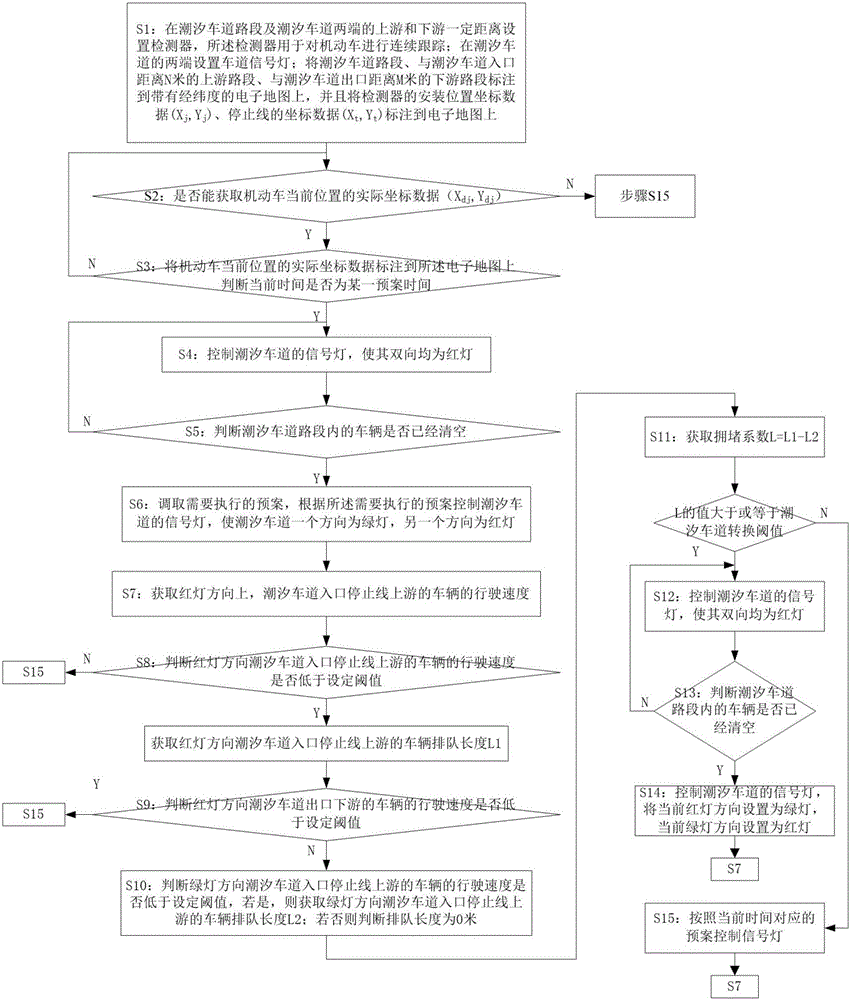
[0055] This embodiment provides a method for controlling tidal lane signal lights based on plane perception detection technology, such as figure 1 shown, including the following steps:

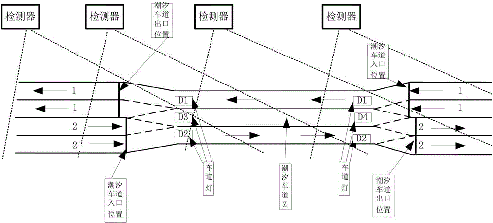
[0056] S1: Install detectors at a certain distance upstream and downstream of the tidal vehicle road section and both ends of the tidal lane, and the detectors are used for continuous tracking of motor vehicles; set up lane signal lights at both ends of the tidal lane; The upstream section of the entrance distance N meters, and the downstream section of the tidal lane exit distance M meters are marked on the electronic map with latitude and longitude, and the installation position coordinate data (X j ,Y j ), the coordinate data of the stop line (X t ,Y t ) marked on the electronic map. Wherein Nm and Mm can be equal or not. The specific selection can be set according to the actual road conditions. For example, 50 meters, 80 meters, etc. can be selected. It should be noted that both the...

Embodiment 2

[0073] Present embodiment has following further optimization on the basis of embodiment 1, the process of determining the current actual position of motor vehicle in described step S2 comprises the following steps:

[0074] S21: Obtain the current detection error of the detector (X c ,Y c ).

[0075] S22: Judging the current detection error (X c ,Y c ) is within the set threshold range, if so then enter step S23, otherwise an alarm signal is sent, prompting that the correction marker position coordinate data cannot be accurately obtained; then enter step S15;

[0076] S23: Obtain the coordinate data of the current position of the motor vehicle (X d ,Y d );

[0077] S24: Obtain the actual coordinate data of the current position of the motor vehicle according to the coordinate data of the current position of the motor vehicle and the current detection error: (X dj ,Y dj )=(X d ,Y d )-(X c ,Y c ).

[0078] Specifically, adaptive adjustments can be made according to d...

Embodiment 3

[0100] This embodiment provides a tidal lane signal light control system based on plane perception detection technology, such as Figure 5 shown, including:


PUM


Abstract

The invention provides a reversible lane signal lamp controlling method and system based on planar perception detection technology, ensures immediate changing of a signal lamp after vehicles in a reversible lane is cleared up, prevents safety risk due to opposite driving and improves road pass efficiency. Queue lengths of vehicles on inlet and outlet at the red-light direction of a reversible lane, and vehicles on inlet at the green-light direction can be detected on a real-time basis to obtain a jamming coefficient. When the queue length at the inlet of the red-light direction, namely jamming coefficient, satisfies changing conditions, the passing direction of the current reversible lane changes to improve the efficiency of vehicles passing the reversible lane. if the vehicles driving speed at the outlet of the red-light direction of the reversible lane is lower than a set threshold, the signal lamp may not change even if the direction changing conditions of the reversible lane are met. Through the reversible lane signal lamp controlling method and system, safety driving of vehicles is ensured, and passing efficiency of a reversible lane is improved.

Description

technical field [0001] The invention relates to the technical field of intelligent transportation, in particular to a method and system for controlling signal lights of tidal lanes based on plane perception detection technology. Background technique [0002] With the continuous expansion of the city scale, it is more and more that residential areas are built in the suburbs, and work units, business districts, and large shopping malls are concentrated in urban areas. As a result, during peak hours in the morning and evening, motor vehicles flow from one direction of the city to another direction, which is a common tidal phenomenon. Another phenomenon is that the construction of urban roads is restricted by various conditions. When a bottleneck occurs on a certain road section, when a tidal phenomenon occurs, the bottleneck road section is congested in one direction, and the lane in the other direction is empty. In order to solve this problem at home and abroad, many solution...

Claims


Application Information

Patent Timeline
Patent Type & Authority Applications(China)
IPC IPC(8): G08G1/08
CPCG08G1/08
Inventor 姜廷顺梁子君宋志洪石勇王家捷陶刚
Owner ANHUI KELI INFORMATION IND
Why Eureka
Try Eureka