motor

A motor and cage technology, applied in the direction of electromechanical devices, electrical components, windings, etc., can solve the problem of assembling motors with a lot of effort, and achieve the effect of high-efficiency electrical connection

Active Publication Date: 2018-12-18
SANKYO SEIKI MFG CO LTD
View PDF1 Cites 0 Cited by
  • Summary
  • Abstract
  • Description
  • Claims
  • Application Information

AI Technical Summary

Problems solved by technology

[0004] However, as in the structure described in Patent Document 1, in the structure in which the ground terminal held by the connector member is connected to the stator core through a wiring member such as a wire, there is a problem that it takes a lot of work to assemble the motor.

Method used


Image

  • motor
  • motor
  • motor

Examples


Embodiment Construction

[0090] Hereinafter, modes for implementing the present invention will be described with reference to the drawings.

[0091] (the whole frame)

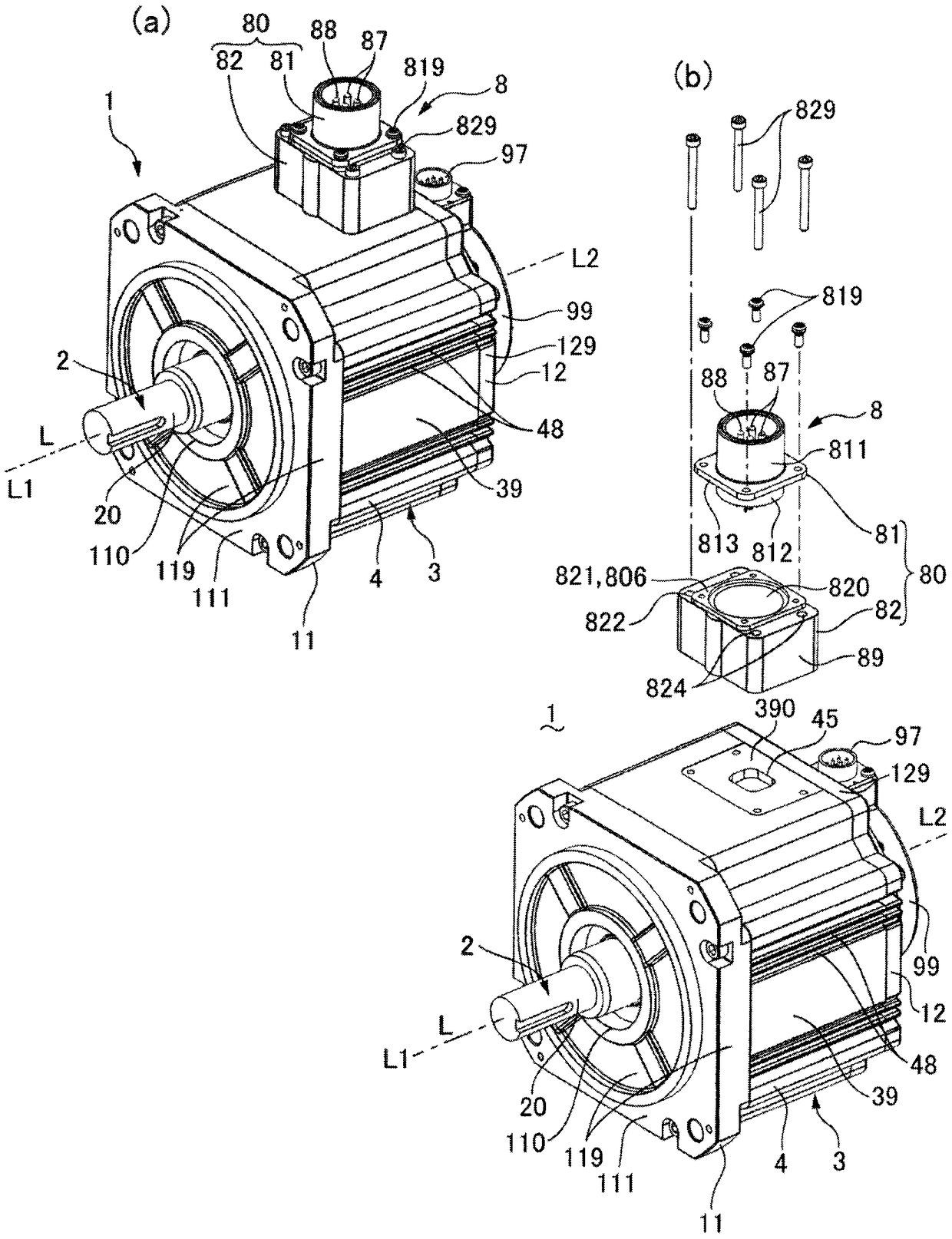
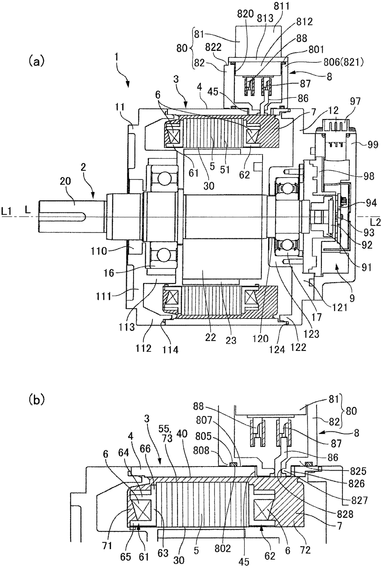
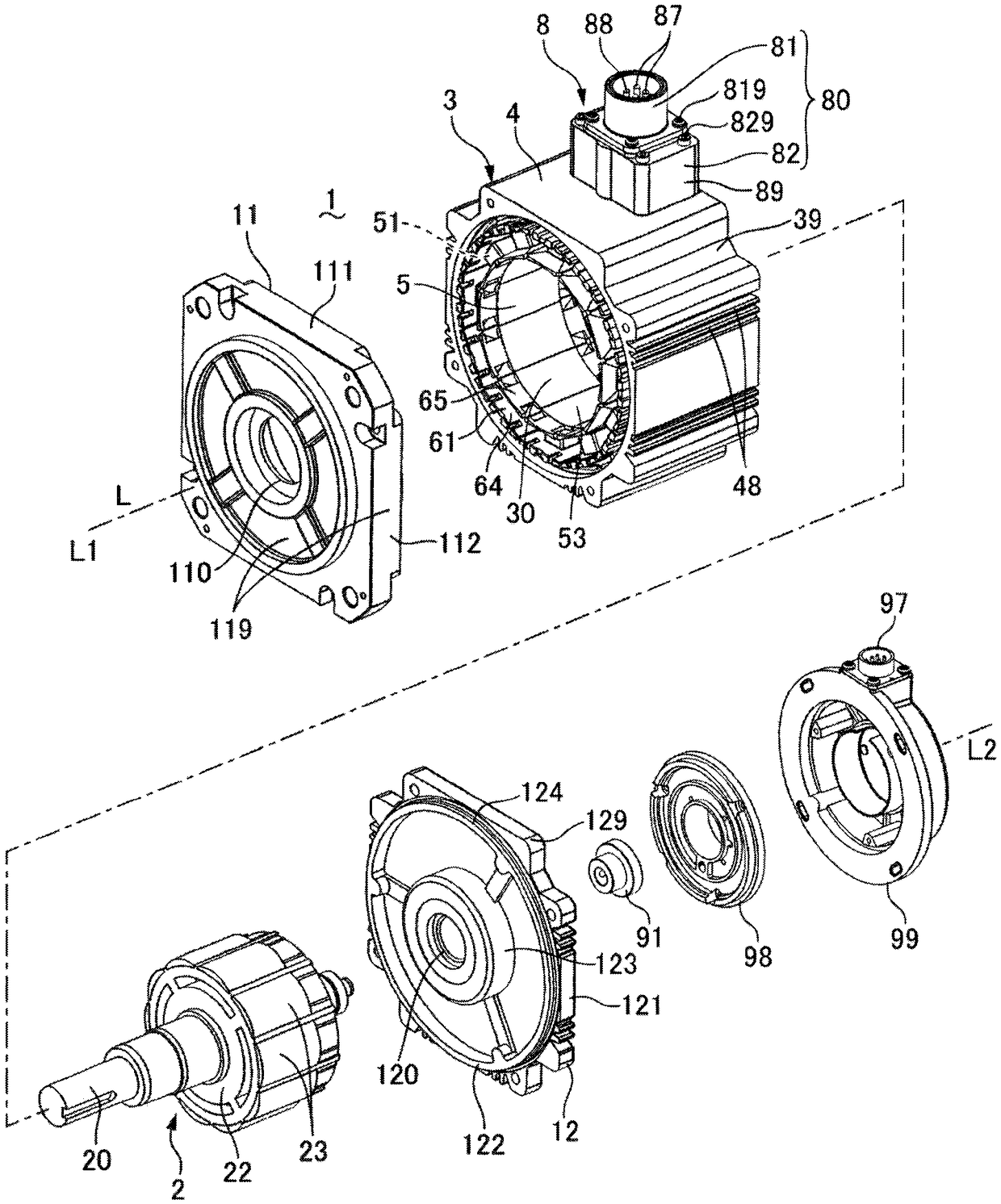
[0092] figure 1 (a), figure 1 (b) is a perspective view of the motor 1 to which the present invention is applied viewed from the output side, figure 1 (a) is a perspective view of the whole motor 1, figure 1 (b) is a perspective view of the state which removed the power supply part 8 from a motor main body. figure 2 (a), figure 2 (b) is a cross-sectional view showing a state where the motor 1 to which the present invention is applied is cut at a position where the motor axis passes. image 3 It is an exploded perspective view of the motor 1 to which the present invention is applied. In addition, in image 3 In , illustration of the molded resin portion 7 is omitted.

[0093] figure 1 (a), figure 1 (b), figure 2 (a), figure 2 (b) and image 3 The motor 1 shown is a permanent magnet type synchronous motor. The motor 1 h...


PUM


Abstract

The present invention provides a motor capable of efficiently electrically connecting a ground terminal to a stator core. In the motor (1), a power feeding portion (8) is provided on the outer peripheral side of a metallic iron core holder (4) holding the stator core (5) inside. A power terminal (87) electrically connected to the stator coil (6) through a wiring member (86) and a ground terminal (88) are held by a metal terminal holder (80) in the power supply unit (8). The ground terminal (88) is electrically connected to the terminal holder (80), and the terminal holder (80) is fixed to the iron core holder (4) in contact with the iron core holder (4). Accordingly, the ground terminal (88) is electrically connected to the stator core (5) through the terminal holder (80) and the iron core holder (4).

Description

technical field [0001] The present invention relates to a motor provided with a power supply unit on the outer peripheral side of a stator. Background technique [0002] In the motor, as a structure for supplying electric power to the stator coil wound on the salient pole of the stator core, a connector member is attached to the outer peripheral side of the stator, and the stator coil is held on the connector member. The structure of the power supply terminal connection. In this case, one end of a wiring member such as a wire is connected to the ground terminal held by the connector member, and the other end of the wiring member is connected to the stator core by bolts or the like (see Patent Document 1). [0003] Patent Document 1: Japanese Patent Application Laid-Open No. 11-289702 [0004] However, in the structure in which the ground terminal held by the connector member is connected to the stator core through a wiring member such as a wire, as in the structure describ...

Claims


Application Information

Patent Timeline
Patent Type & Authority Patents(China)
IPC IPC(8): H02K3/50H02K15/12H02K3/34
CPCH02K3/345H02K3/50H02K15/12
Inventor 山本登子雄
Owner SANKYO SEIKI MFG CO LTD
Why Eureka
Try Eureka