Micromechanical sensor

A micromechanical sensor, micromechanical technology, applied in instruments, microstructure technology, electric solid devices, etc., can solve problems such as sensor enlargement

Pending Publication Date: 2022-03-29
ROBERT BOSCH GMBH
View PDF0 Cites 0 Cited by
  • Summary
  • Abstract
  • Description
  • Claims
  • Application Information

AI Technical Summary

Problems solved by technology

[0004] However, a plurality of analysis processing chips leads to an enlargement of the housing and thus of the sensor, which is undesirable

Method used


Image

  • Micromechanical sensor
  • Micromechanical sensor
  • Micromechanical sensor

Examples


Embodiment Construction

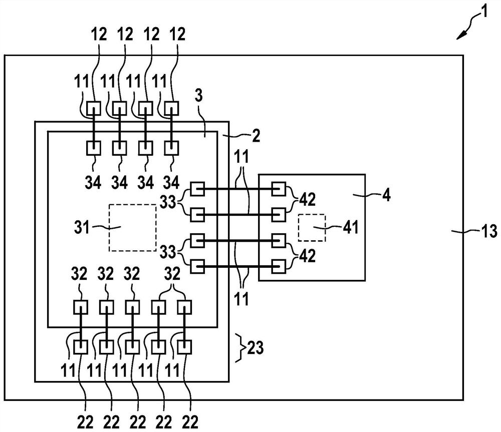
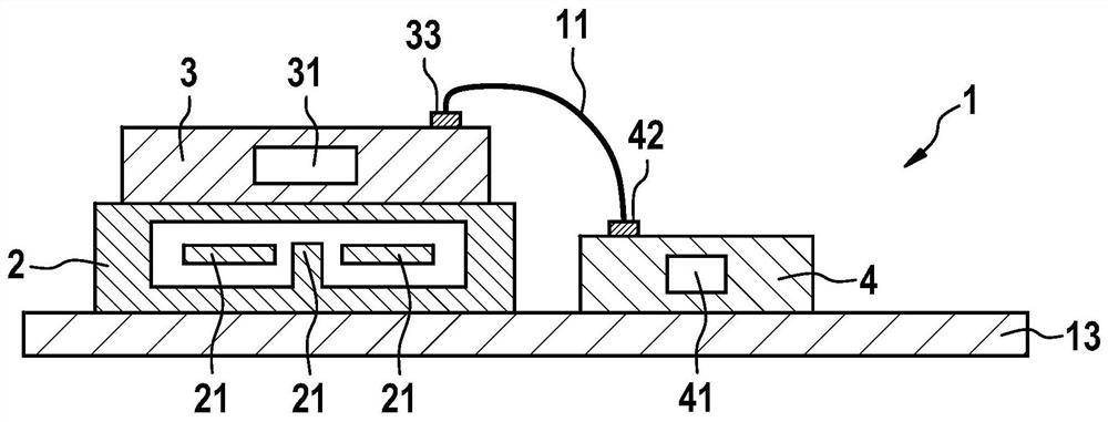
[0027] figure 1 A micromechanical sensor 1 is shown, which has a micromechanical chip 2 with a first micromechanical structure, which also has a first evaluation chip 3 and a second evaluation chip 4 , The first analysis and processing chip has a first application specific integrated circuit 31 , and the second analysis and processing chip has a second application specific integrated circuit 41 . The micromechanical chip 2 is arranged here on an optional substrate 13 . The first evaluation chip 3 and the micromechanical chip 2 are arranged one above the other, ie stacked on top of each other. The micromechanical chip 2 is electrically conductively connected to the first evaluation chip 3 . The connection is at figure 1 The process is carried out by means of bonding wires 11 leading from the chip pad 22 of the micromechanical chip 2 to the chip pad 32 of the first evaluation chip 3 . It is also possible to provide other conductive connections (e.g. via vias or direct bondin...


PUM


Abstract

The invention relates to a micromechanical sensor, comprising a micromechanical chip, which has a first micromechanical structure, a first evaluation chip, which has a first application-specific integrated circuit, and a second evaluation chip, which has a second application-specific integrated circuit, which has a second application-specific integrated circuit. The second analyzing and processing chip is provided with a second application-specific integrated circuit. The first evaluation chip and the micromechanical chip are arranged in a stacked manner, the micromechanical chip being directly connected to the first evaluation chip in an electrically conductive manner, and the first evaluation chip being directly connected to the second evaluation chip in an electrically conductive manner. The first special-purpose integrated circuit mainly comprises analog circuit elements, and the second special-purpose integrated circuit mainly comprises digital circuit elements.

Description

technical field [0001] The invention relates to a micromechanical sensor. Background technique [0002] Micromechanical sensors for measuring, for example, acceleration, rotational speed, pressure and other physical variables are produced in series for various applications in, for example, the automotive and consumer sectors. Combined rotational speed and acceleration sensors installed in a common housing play an increasingly important role. The combination of a three-axis rotational speed sensor and a three-axis acceleration sensor is also called an IMU (Inertial Measurement Unit, inertial measurement unit). [0003] Micromechanical chips, also called MEMS chips, can be used in the sensors. In this case, the micromechanical chip can include a microelectromechanical system. The sensor can also include an evaluation chip or a plurality of evaluation chips, which can be designed, for example, as an ASIC (Application Specific Integrated Circuit). [0004] However, a plurali...

Claims


Application Information

Patent Timeline
Patent Type & Authority Applications(China)
IPC IPC(8): B81B7/00B81B7/02G01P15/18G01C19/00G01P3/00
CPCB81B7/0032B81B7/007B81B7/02G01P15/18G01C19/00G01P3/00B81B2201/02B81B2201/0235B81C2203/0154B81C2203/0792B81B2207/012B81B2201/0242B81C1/0023B81B2207/03
Inventor A·维斯孔蒂A·科索夫J·哈恩J·克拉森T·吉塞尔曼
Owner ROBERT BOSCH GMBH
Why Eureka
Try Eureka