Container for fuel cell, fuel cell and electronic device

A fuel cell and container technology, which is applied to fuel cells, fuel cell components, solid electrolyte fuel cells, etc., can solve the problems of hindering the electrochemical reaction of electrolyte components 23, difficult to realize small fuel cells, and deterioration of power generation efficiency. Improve mechanical reliability, high reliability and safety, good corrosion resistance

Inactive Publication Date: 2005-02-23
KYOCERA CORP
View PDF2 Cites 0 Cited by
  • Summary
  • Abstract
  • Description
  • Claims
  • Application Information

AI Technical Summary

Problems solved by technology

However, in the conventional fuel cell 21, since electric power is taken out from the fuel electrode 24 and the air electrode 25 sandwiching the electrolyte member 23, the only methods that can be used to pull out the gas separator 26 for external connection or make the gas separator 26 a conductive material and coincident series connection method, which has the problem of being difficult to implement in small fuel cells
[0024] Moreover, water (H 2 O) The air flow path 29 will be blocked, so it becomes difficult to supply air as an oxidant gas from the atmosphere to the air electrode 25 through the air flow path 29, thereby hindering the electrochemical reaction at the electrolyte member 23, thereby degrading the power generation efficiency.

Method used


Image

  • Container for fuel cell, fuel cell and electronic device
  • Container for fuel cell, fuel cell and electronic device
  • Container for fuel cell, fuel cell and electronic device

Examples


Embodiment Construction

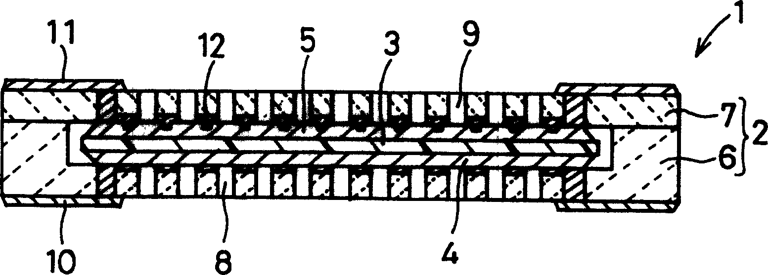
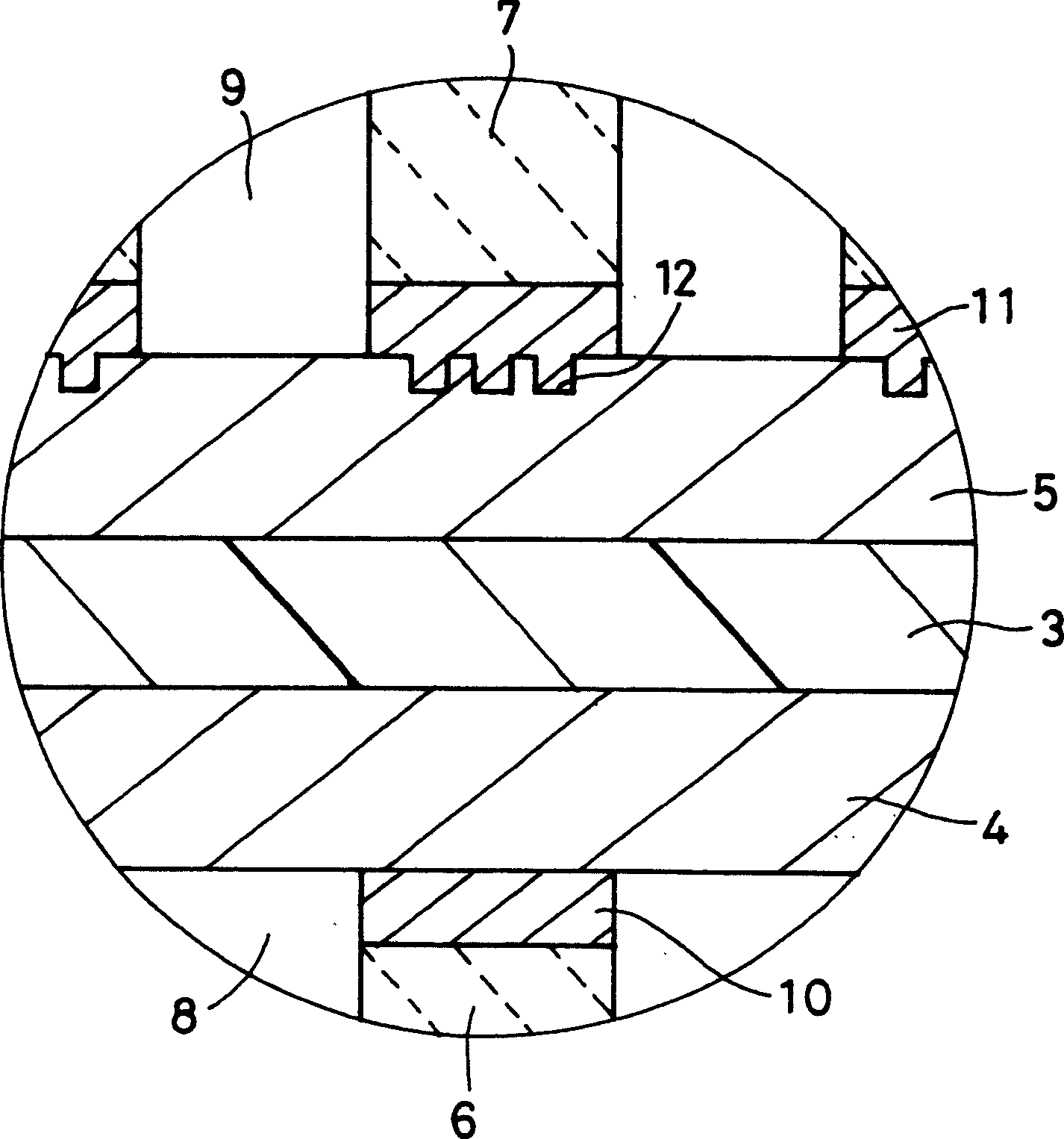
[0060] The fuel cell container and fuel cell of the present invention will be described in detail below with reference to the drawings. figure 1 Is a cross-sectional view showing an example of an embodiment of a fuel cell using the fuel cell container of the present invention, figure 2 Yes figure 1 Enlarged view of the main part. In these figures, 1 is a fuel cell, 2 is a fuel cell container, 3 is an electrolyte component, 4 is a first electrode, 5 is a second electrode, 6 is a substrate, 7 is a cover, and 8 is a first fluid flow path , 9 is a second fluid flow path, 10 is a first wiring conductor, 11 is a second wiring conductor, and 12 is a pit.

[0061] and, figure 1 It shows a fuel cell in which a pit 12 is formed at each contact portion of the second electrode 5 and the lid 7, respectively, figure 2 This shows a fuel cell in which three pits 12 are formed in each contact portion of the second electrode 5 and the lid 7.

[0062] In the electrolyte member 3, a fuel electro...


PUM

PropertyMeasurementUnit
bending strengthaaaaaaaaaa
thicknessaaaaaaaaaa
depthaaaaaaaaaa

Abstract

This fuel cell container is equipped with a substrate 6 having a recessed part to house the electrolyte member 3 having first and second electrodes 4, 5, a first fluid passage 8 formed from the bottom surface of the recessed part on to the external surface of the substrate 6, a first wiring conductor 10 one end of which is disposed on the bottom surface of the recessed part and the other end of which is led out to the external surface of the substrate 6, a lid body 7 attached to the upper surface of the periphery of the recessed part of the substrate 6, a second fluid passage 9 formed from the lower surface of the lid body 7 on to its external surface, and a second wiring conductor 11 one end of which is disposed on the lower surface of the lid part 7 and the other end of which is led out to the external surface of the lid part 7, and a recessed part 12 is formed in either one of the contact part where the first electrode 4 is brought into contact with the substrate 6 or the contact part where the second electrode 5 is brought into contact with the lid part 7.

Description

Technical field [0001] The present invention relates to a small and highly reliable fuel cell container made of ceramics capable of accommodating electrolyte components, and a fuel cell and electronic equipment using the container. Background technique [0002] In recent years, the development of small fuel cells that operate at lower temperatures than before has been actively carried out. Among the fuel cells, depending on the type of electrolyte used, a polymer electrolyte fuel cell (Polymer Electrolyte Fuel Cell: hereinafter referred to as PEFC), a phosphoric acid fuel cell, or a solid electrolyte fuel cell is known. [0003] Among them, the working temperature of PEFC is a low temperature of about 80-100°C, and it has the following remarkable features, namely: [0004] (1) With high output density, miniaturization and light weight can be achieved. [0005] (2) Since the electrolyte is non-corrosive and the operating temperature is low, there are few restrictions on battery co...

Claims


Application Information

Patent Timeline
Patent Type & Authority Applications(China)
IPC IPC(8): H01M8/02H01M8/06H01M8/10
CPCY02E60/521Y02E60/50H01M8/006H01M8/0247H01M8/0258H01M8/0273
Inventor 菅井广一朗
Owner KYOCERA CORP
Why Eureka
Try Eureka