Method and system for controlling constant temperature for fuel cells

a fuel cell and constant temperature technology, applied in the assembly system of the fuel cell, electrochemical generators, indirect heat exchangers, etc., can solve the problems of difficult manufacturing, complicated structure and manufacturing, and the inability to manufacture portable 3c electronic products or even smaller electronic devices, so as to reduce the temperature of the anode fuel, increase the temperature of the heat sink, and reduce the temperature of the fuel cell

Inactive Publication Date: 2005-04-14
ANTIG TECH CO LTD
View PDF4 Cites 28 Cited by
  • Summary
  • Abstract
  • Description
  • Claims
  • Application Information

AI Technical Summary

Benefits of technology

[0006] To achieve this objective, the present invention utilizes a constant temperature control system for the use of the fuel cell systems. The fuel cell system has one or more fuel cell core component and a temperature / fuel sensing layer coupled to the upper side of the anode of the fuel cell core component, providing flow space for the anode fuel during the anode action of the fuel cell core component. The constant temperature control system comprises one or more heat pipe at least partially placed on the temperature / fuel sensing layer. The first end of the heat pipe extends into the temperature / fuel sensing layer to conduct the heat produced during the anode action of the fuel cell core component to the other end of the heat pipe. The constant temperature control system also comprises a heat sink connected to the second end of the heat pipe, a heat-dispersing device to disperse the heat of the heat sink to lower the heat sink's temperature, a heating device to increase the temperature of the heat sink, and also a temperature control processing unit. Temperature control processing unit is used to detect the temperature and the heat generated during the anode action of the fuel cell core component, and to activate the heat-dispersing device to disperse the heat of the heat sink to lower the anode fuel's temperature if the anode fuel's temperature is higher than a predetermined temperature range. The temperature control processing unit is also used to activate the heating device to increases the temperature of the heat sink, thereby increasing the anode fuel's temperature, if the anode fuel's temperature falls lower than a predetermined temperature range. By using the constant temperature control system to keep the temperature of the anode fuel within a predetermined temperature range, the effectiveness of the fuel cell core component's anode action is increased.
[0007] Furthermore, to achieve the aforementioned objective, the present invention provides a method for controlling the constant temperature of the fuel cell systems, applicable to fuel cell systems with one or more fuel cell core component and at least one temperature / fuel sensing layer coupled onto the anode of the fuel cell core component. The temperature / fuel sensing layer provides flowing space for the anode fuel during the fuel cell core component's anode action. This method comprises the following: one or more heat pipe at least partially placed in the temperature / fuel sensing layer. The first end of the heat pipe is extended into the interior of the temperature / fuel sensing layer to conduct the heat produced in the fuel cell core component's anode action to the second end of the heat pipe; a heat sink, connected to the second end of the heat pipe; a heat dispersing device that disperses the heat of the heat sink to lower the temperature of the heat sink, and a heating device that heats the heat sink to increase the temperature of the heat sink. There is also a temperature control processing unit that detects the temperature of the heat produced in the anode action of the fuel cell core component, and activates the heat dispersing device to disperses the heat of the heat sink to lower anode fuel's the temperature if the anode fuel's temperature is higher than a predetermined temperature range. This unit further activates a heating device to increase the temperature of the heat sink and the temperature of anode fuel if the anode fuel's temperature is lower than a predetermined temperature range. By using the above steps to control the temperature of the anode fuel within a predetermined temperature range, the efficiency of the anode action of the fuel cell core computer should increase.

Problems solved by technology

Also, the flow plate and the fuel cell assembly system disclosed in the U. S. Pat. No. 6,146,779 are structurally complicated and difficult to manufacture.
Further, due to the structural characteristics of the fluid flow plate of U.S. Pat. No. 6,146,779, the design of the temperature control system for the fuel cell assembly system is more suited for larger systems, but inappropriate for small and portable 3C electronic products or even smaller electronic devices.
However, U. S. Pat. No. 6,598,397 applies to generating electric power from heat dissipation wasted heat, unrelated to constant temperature control.

Method used


Image

  • Method and system for controlling constant temperature for fuel cells
  • Method and system for controlling constant temperature for fuel cells
  • Method and system for controlling constant temperature for fuel cells

Examples


Embodiment Construction

[0013] The detailed description and technical characteristics of the present invention are described together with the drawings as follows.

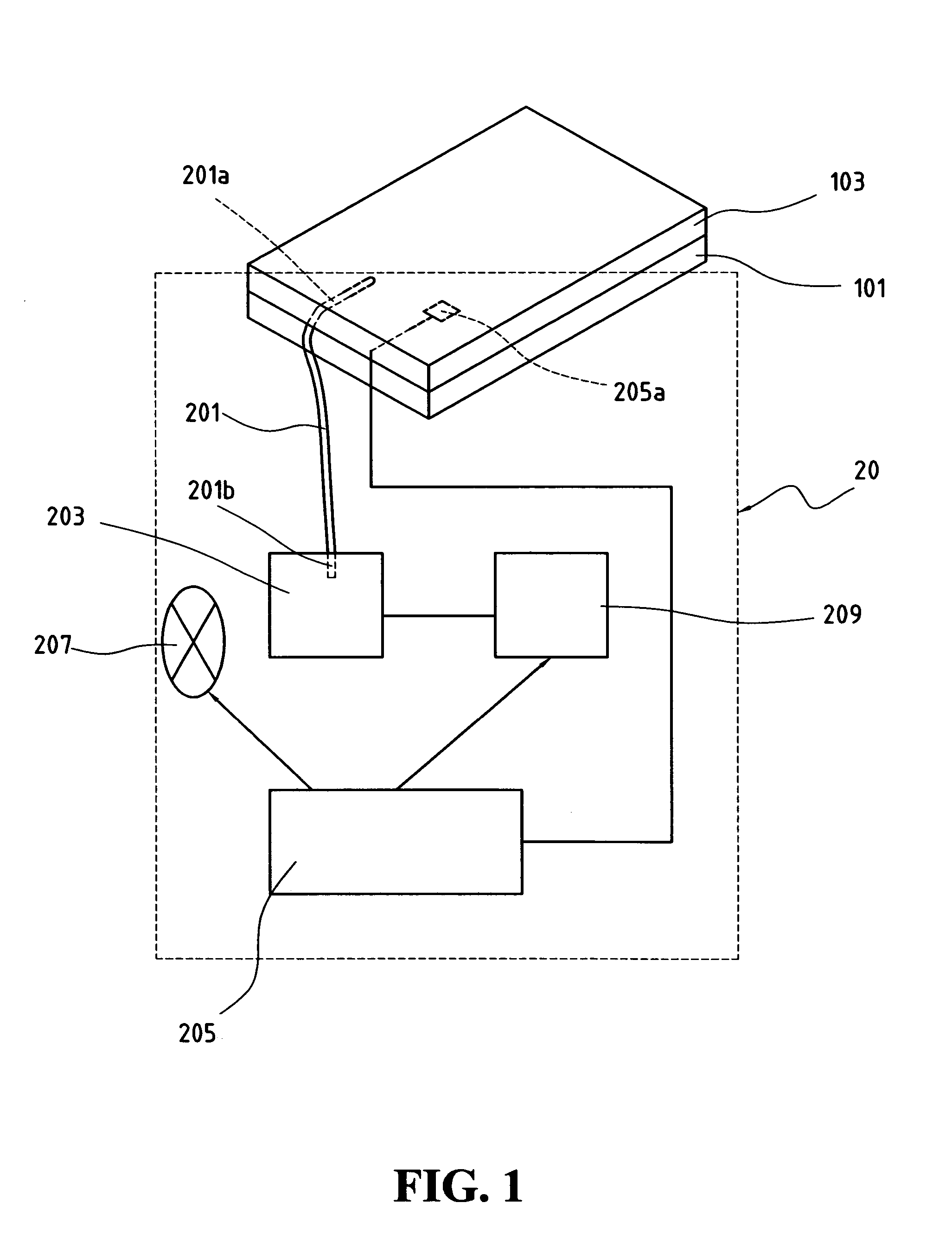
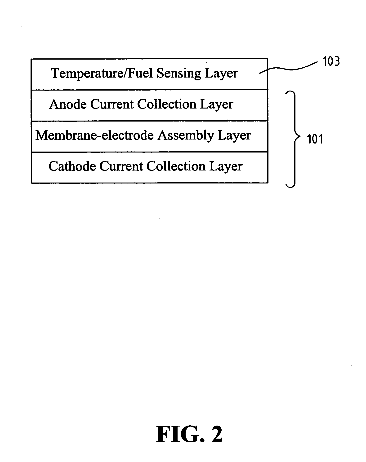
[0014] Please refer to FIG. 1 for the structural diagram of the constant temperature control system for fuel cell systems according to the present invention. The constant temperature control system 20 of the invention is applied in a fuel cell system 10. Because fuel cell core component 101 produces heat during chemical reaction, the amount of heat generated leads to considerably high temperature, especially if a plurality of the fuel cell core components 101 is connected in series or in parallel to jointly generate electricity. If such a temperature were not properly controlled, it would adversely affect the fuel cell system 10. Please refer to FIG. 2 for the structural diagram of the fuel cell core component of the present invention. The upper side of the anode of the fuel cell core component 101 is coupled to the temperature / fuel sensing laye...


PUM

PropertyMeasurementUnit
temperatureaaaaaaaaaa
constant temperatureaaaaaaaaaa

Abstract

This invention relates to a constant temperature control system for fuel cell systems. The first end of the heat pipe is extended into the interior of the temperature / fuel sensing layer in order to conduct the heat produced during the anode action of the fuel cell core component to the second end of the heat pipe. The second end of the heat pipe is connected to a heat sink. A device is used to disperse the heat and lower the temperature of the heat sink and a device to increase the temperature of the heat sink. A temperature control processing unit that detects the temperature and heat produced in the anode action of the fuel cell core component. As a result, the constant temperature control system keeps the temperature of the anode fuel within a predetermined temperature range, and increases the effectiveness of the anode action of the fuel cell core component.

Description

FIELD OF THE INVENTION [0001] The present invention is related to a method and a system for controlling the temperature of a fuel cell system during its operations, particularly a method and a system of controlling and / or maintaining a constant temperature so that the anode fuel of a fuel cell system is controlled and / or maintained at a predetermined temperature range during the fuel cell system's operations. BACKGROUND OF THE INVENTION [0002] The U.S. Pat. No. 6,146,779 entitled “Fluid flow plate, fuel cell assembly system, and method employing same for controlling heat in fuel cells” disclosed a method of using a heat pipe to control the heat of a fuel cell system. Although the U.S. Pat. No. 6,146,779 disclosed implementing a temperature control mechanism in fuel cell systems, it does not comprise a function for constant temperature control. Also, the flow plate and the fuel cell assembly system disclosed in the U. S. Pat. No. 6,146,779 are structurally complicated and difficult t...

Claims


Application Information

Patent Timeline
Patent Type & Authority Applications(United States)
IPC IPC(8): F28D15/02H01M8/02H01M8/04
CPCF28D15/0266H01M8/04007H01M8/04067H01M8/04074H01M8/04328Y02E60/50H01M8/04708H01M8/04723H01M8/04731H01M8/04768H01M8/1011H01M8/04365
Inventor SHU, HSI-MINGDENG, FENG-YIKUAN, YEAN-DERJAN, JING-TANG
Owner ANTIG TECH CO LTD
Why Eureka
Try Eureka