A battery row, a battery pack and a manufacturing method thereof

A manufacturing method and battery row technology, applied to battery pack components, circuits, electrical components, etc., can solve problems such as small laser energy concentration points, damage, and failure to meet reliable electrical connections, and achieve good contact resistance consistency and high The effect of electrical connection stability

Active Publication Date: 2022-05-17
JIAXING MODULE BONDING TECH CO LTD
View PDF0 Cites 0 Cited by
  • Summary
  • Abstract
  • Description
  • Claims
  • Application Information

AI Technical Summary

Problems solved by technology

However, the energy concentration point of the laser is small, and the flatness requirements for multi-battery poles on the same plane are high during welding, otherwise it is easy to cause insufficient welding or over-welding (battery shell damage)
Since there is a certain tolerance in the height of the crimping connection between the top cover of the cylindrical battery and the shell, there is a certain tolerance in the height between the top pole and the shell pole at the bottom of the shell. After aligning one pole and fixing the structure by the bus bar, another The poles on one side are difficult to realign
If the laser welding process continues to be used on the other side, the welding yield will be greatly reduced (about 70%), which cannot meet the needs of reliable electrical connections on both sides, and it is difficult to promote the method of welding on both sides with laser welding.
[0004] Due to the above-mentioned problem of heat welding that is difficult to balance the efficiency and yield rate, in the process of forming cylindrical batteries, it has become a fast and reliable process implementation method to find electrical connections such as positive parallel connection, negative parallel connection and row-to-row series connection. Research Direction of Grouped Electrical Connection of Multi-Battery Arrays

Method used


Image

  • A battery row, a battery pack and a manufacturing method thereof
  • A battery row, a battery pack and a manufacturing method thereof
  • A battery row, a battery pack and a manufacturing method thereof

Examples


Embodiment 1

[0074] This example 1 provides a battery row with a composite electrical connection process, which is used to prepare the single cylindrical battery 1 into a CTP module that is connected in parallel within the row and connected in series between the rows, and is especially suitable for the preparation process of new energy vehicle power battery units. And it is also applicable to low-speed electric vehicles, electric bicycles and other energy storage products.

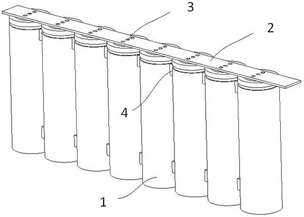
[0075] according to Figure 1-Figure 3 , a battery row of this embodiment, that is, a battery row using a composite electrical connection process, the battery row is one of the basic units in the power battery module, including:

[0076] A plurality of single cylindrical batteries 1, a plurality of single cylindrical batteries 1 are arranged in rows; single cylindrical batteries 1 include top poles and side shell poles; the top poles are made of metal conductive materials; battery rows All the single cylindrical batte...

Embodiment 2

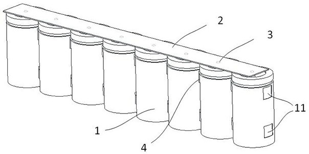
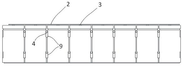
[0089] This example 2 provides a battery row with a composite electrical connection process, and the difference from the example 1 is mainly reflected in the structure of the bus bar 2 . according to Figure 4-Figure 5 The busbar 2 includes a bent confluence part 21 disposed at the end, and the bent confluence part 21 is located outside the two ends of the battery row. The bent busbar 21 may be present at both ends, or only at one end of the bus bar 2 .

[0090] The functions of the bending confluence part 21 include but are not limited to undertake the function of electrical connection with other battery rows, which is equivalent to placing the outer top pole sideways. The function of the bending confluence part 21 also includes constraining the longitudinal gap of the battery row to a certain extent.

[0091] Preferably, according to Figure 5 There is a certain distance between the bent confluence part 21 and the side housing pole of the single cylindrical battery 1 at t...

Embodiment 3

[0093] according to Figure 6-Figure 9 , this example 3 provides a composite electrical connection process battery pack, including a plurality of arrays of any one of the battery rows disclosed in the above embodiments, the battery row of the battery pack is connected in parallel, and the adjacent battery rows are connected in series.

[0094] At least part of the side housing poles of the battery row serve as outer housing poles of the battery row.

[0095] As a preferred embodiment, it also includes a plurality of case pole lead bridges 7, each case pole lead bridge 7 is electrically connected to a side case pole of a battery row.

[0096] The outer casing pole of each battery row is electrically connected to the bus bar 2 of the adjacent battery row in turn, and the adjacent battery rows are connected in series; the bus bar 2 of the first battery row is used as the outer top pole of the battery pack.

[0097] As a preferred implementation manner, at least one structural gl...


PUM


Abstract

The invention relates to a battery row, a battery pack and a manufacturing method thereof. The battery row includes a plurality of single cylindrical batteries arranged in rows; the single cylindrical battery includes top poles and side shell poles; all single cylindrical batteries in the battery row are arranged in the same direction; The top poles of each single cylindrical battery are set, and the top poles of each single cylindrical battery are electrically connected to the bus bar by heat welding; the side shell poles of adjacent single cylindrical batteries are connected At least one cold welding structure is set between them; all single cylindrical batteries in the battery row are in parallel structure. The present invention adopts the process of composite welding, and the heat welding process is adopted between the top pole of each single cylindrical battery and the bus bar, and all the solder joints are made with extremely high efficiency, and every two adjacent single cylindrical batteries The cold welding process is used between the poles of the side shell of the battery to efficiently complete the electrical connection of the poles of the shell.

Description

technical field [0001] The invention relates to the field of new energy power batteries, in particular to a battery row, a battery pack and a manufacturing method thereof. Background technique [0002] With the continuous development of the new energy industry, the market demand for power battery modules continues to expand, which puts forward higher requirements for the production efficiency of power battery modules. [0003] The process of grouping multiple single cylindrical batteries is one of the main technical branches of power battery modules. The series-parallel electrical connection process of cylindrical battery packs usually uses the same electrical connection process for the parallel connection of the top poles and the parallel connection of the shell poles. The industry usually adopts the method of fusion and heat welding of the bus bar and the battery pole metal. Among them, heat welding methods are usually spot welding, laser welding and ultrasonic welding. ...

Claims


Application Information

Patent Timeline
Patent Type & Authority Patents(China)
IPC IPC(8): H01M50/516H01M50/507H01M50/509H01M50/258H01M50/213
CPCH01M50/516H01M50/507H01M50/509H01M50/258H01M50/213Y02E60/10
Inventor 汪波刘存良杨钢
Owner JIAXING MODULE BONDING TECH CO LTD
Why Eureka
Try Eureka