
Looping bridge for looping through a number of electric signals

A technology of electrical signal and energized bridge, which is applied to the installation of electrical components, conductive connections, cables, etc., can solve the problems of complicated process and time-consuming, and achieve the effect of efficient electrical contact

Active Publication Date: 2016-08-24
PHOENIX CONTACT GMBH & CO KG
View PDF6 Cites 2 Cited by
  • Summary
  • Abstract
  • Description
  • Claims
  • Application Information

AI Technical Summary

Problems solved by technology

[0003] However, the process of inserting the end of the connecting wire into the connecting device is complex and time-consuming, especially when multiple electrical signals need to be conducted to the electrical contacts of multiple other electrical modules.

Method used


Image

  • Looping bridge for looping through a number of electric signals
  • Looping bridge for looping through a number of electric signals
  • Looping bridge for looping through a number of electric signals

Examples


Embodiment approach

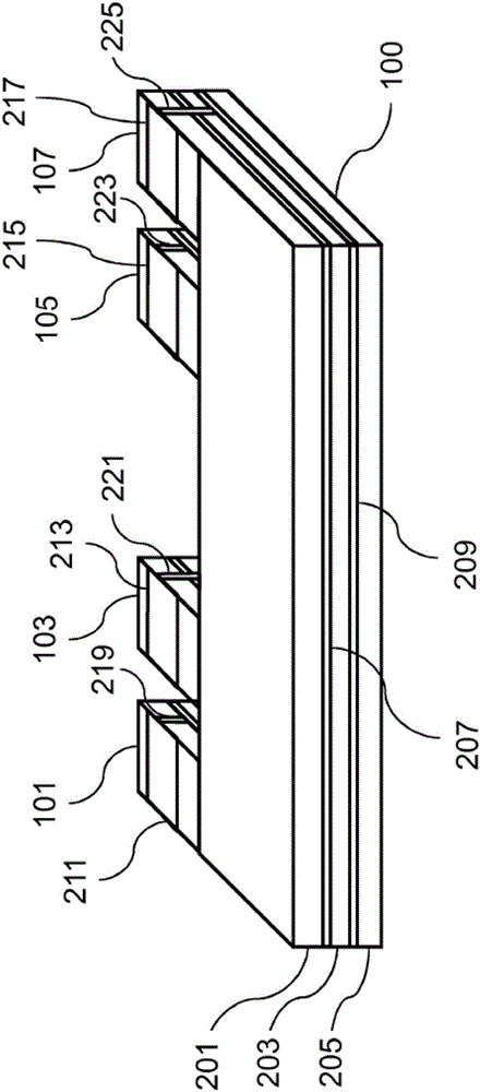
[0108] According to one embodiment, contact surfaces 211 , 213 , 215 , 217 or connection pads are formed on both sides.

[0109] According to one embodiment, the contact surface of the comb-shaped interconnection structure 100 may contact the contact surface of another comb-shaped structure 411 , or may contact the contact surface after the terminal 407 or the above-mentioned terminal is screwed.

[0110] According to one embodiment, the comb-shaped interconnection structure 100 may be implemented as a circuit board or a flexible circuit board.

[0111] According to one embodiment, the comb-shaped interconnection structure 100 has a small installation depth, low cost, short assembly time, compact structure, can have any number of devices, and is not a prefabricated structure.

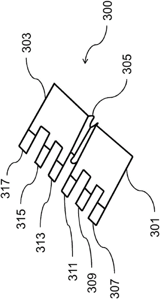
[0112] According to one embodiment, a portion of the comb-shaped interconnect structure 300, such as the flex circuit board portion 305 or the central portion, may be implemented as a flexible portion to ...


PUM


Abstract

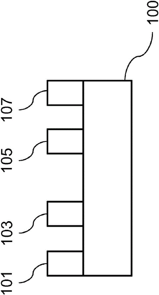
The invention relates to a looping bridge for looping-through a number of electric signals from a first electric module comprising the number of first electric connections to a second electric module comprising the number of second electric connections, comprising: a comb-shaped conducting structure (100) comprising the number of first comb teeth (101, 103) and the number of second comb teeth (105, 107). The first comb teeth (101, 103) can be inserted into the first electric connections, and the second comb teeth (105, 107) can be inserted into the second electric connections. The first comb teeth (101, 103) are connected to the second comb teeth (105, 107) in an electrically conductive manner, said comb-shaped conducting structure (100) being formed by a comb-shaped circuit board.

Description

technical field [0001] The invention relates to a conducting bridge for conducting a certain number of electrical signals. Background technique [0002] When transmitting electrical signals such as power supply voltage to electrical contacts of electrical modules, connecting wires such as insulated copper wires with a cross-sectional area of ​​1.5 square millimeters are often used. When conducting one of the above-mentioned electrical signals to the electrical contact of another electrical module, it is usually necessary to insert the end of each of the two connecting wires into a connecting device such as a double-core wire terminal sleeve to achieve these Electrical connection of connecting wires. When the connecting device is in electrical contact with the electrical contact of the electrical module, one of the electrical signals can be conducted to the electrical contact of the other electrical module. [0003] However, the process of inserting the connecting wire end ...

Claims


Application Information

Patent Timeline
Patent Type & Authority Applications(China)
IPC IPC(8): H01R31/08H02B1/20H02G5/00H01R9/26
Inventor 埃尔玛·沙佩尔
Owner PHOENIX CONTACT GMBH & CO KG
Learn More