Check patentability & draft patents in minutes with Patsnap Eureka AI!

Road indicating lamp remote monitoring system

A remote monitoring system and indicator light technology, applied in lighting devices, light sources, electrical components, etc., can solve problems such as ineffective processing, limited number of management personnel, road traffic paralysis, etc., to meet the needs of traffic lights, optimize Road lights, the effect of ensuring the service life

Inactive Publication Date: 2016-11-09
苏州华安普电力科技股份有限公司
View PDF6 Cites 0 Cited by
  • Summary
  • Abstract
  • Description
  • Claims
  • Application Information

AI Technical Summary

Benefits of technology

This patented technology uses lights like LEDs instead of traditional lamps used on roads or signs. It also includes cameras working under visible weather conditions without being affected by rainwater damage from snow falling onto them during winter months. Additionally, there are supports made up of sturdy iron bars that provide sufficient power while still providing stability. These technical features improve efficiency over existing systems but save more electrical energy compared to older technologies such as incandesence bulbs.

Problems solved by technology

The technical problem addressed by this patented technology relates to managing roads that are becoming increasingly crowded during times when there may be fewer vehicles on them or if they fail unexpectedly causing delays for other drivers. This can cause issues such as reduced visibility caused by poor light conditions near busy intersections where no vehicle has been found within certain distance from their current location.

Method used


Image

  • Road indicating lamp remote monitoring system
  • Road indicating lamp remote monitoring system

Examples


Embodiment Construction

[0014] The following will clearly and completely describe the technical solutions in the embodiments of the present invention with reference to the accompanying drawings in the embodiments of the present invention. Obviously, the described embodiments are only some, not all, embodiments of the present invention. Based on the embodiments of the present invention, all other embodiments obtained by persons of ordinary skill in the art without making creative efforts belong to the protection scope of the present invention.

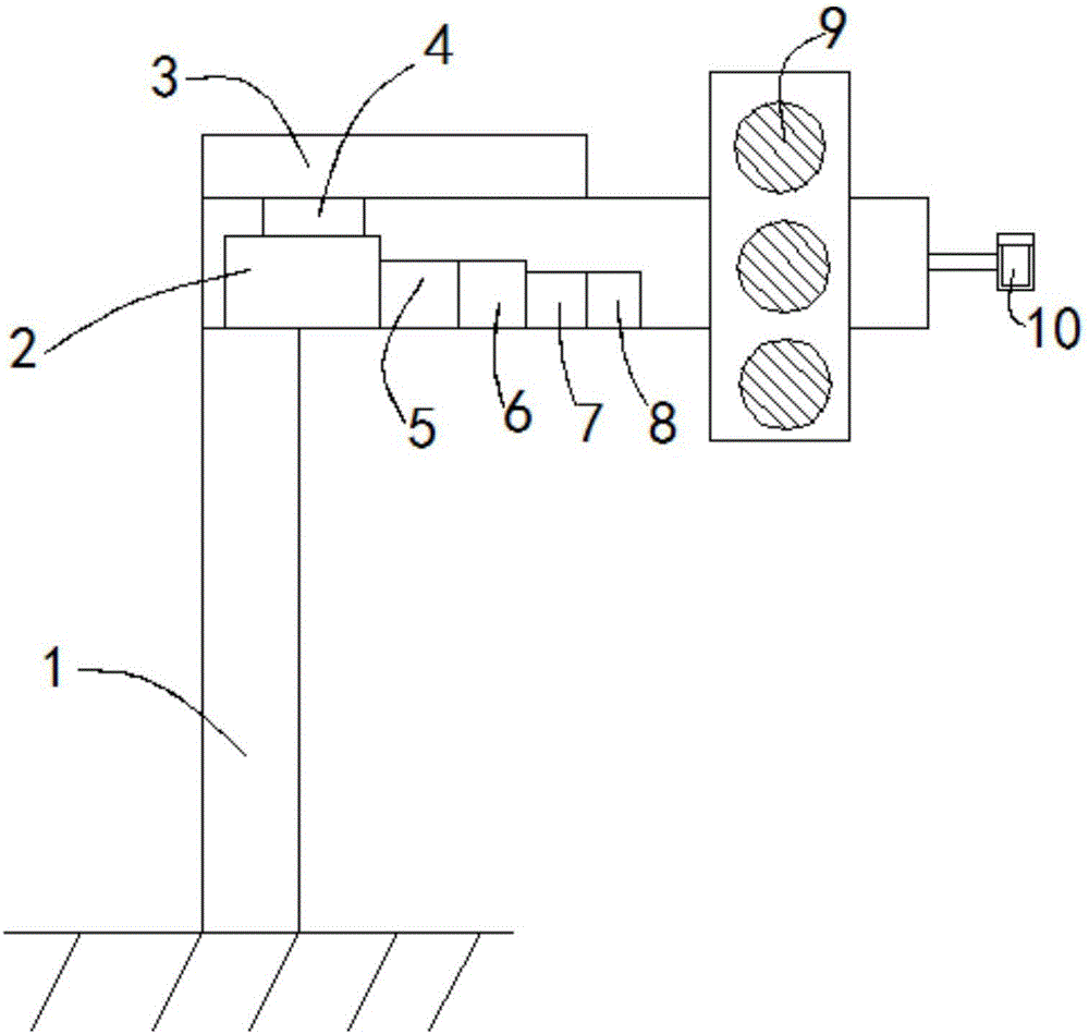
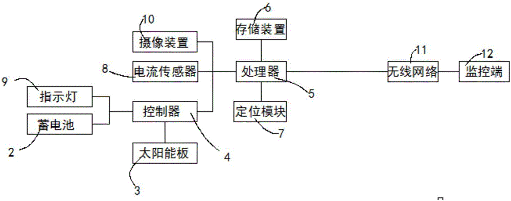
[0015] see Figure 1-2 , the present invention provides a technical solution: a road indicator light remote monitoring system, including a support rod 1, a battery 2, a solar panel 3, a controller 4, a processor 5, a storage device 6, a positioning module 7, a current sensor 8, Indicator light 9, camera device 10, wireless network 11 and monitoring terminal 12, described support rod 1 is a 7-type rod, and the upper end of described support rod 1 is provided wi...


PUM

PropertyMeasurementUnit
Sizeaaaaaaaaaa

Abstract

The invention discloses a road indicating lamp remote monitoring system, which comprises a supporting rod, a storage battery, a solar panel, a controller, a processor, a storage device, a positioning module, a current sensor, an indicating lamp, a camera device, a wireless network and a monitoring terminal. The supporting rod is a 7 type rod. The upper end of the supporting rod is provided with the solar plate. The right end of a cross bar of the supporting rod is provided with the indicating lamp. The right end of the indicating lamp is provided with the camera device. The storage battery, the controller, the processor, the storage device, the positioning module, and the current sensor are arranged in the interior of the cross bar of the supporting rod. The solar panel is connected with the storage battery and the indicating lamp through the controller. When the road indicating lamp breaks down, the road indicating lamp can be found immediately by arranging the current sensor. Former road indicating lamps can be greatly optimized, and the demands on traffic indicating lamps from traffic departments are satisfied.

Description


Claims


Application Information

Patent Timeline
Owner 苏州华安普电力科技股份有限公司
Features
  • R&D
  • Intellectual Property
  • Life Sciences
  • Materials
  • Tech Scout
  • Unparalleled Data Quality
  • Higher Quality Content
  • 60% Fewer Hallucinations
Learn More