Electronic device and watch chain shaft mechanism thereof

A watch chain and hinge structure technology, which is applied in the direction of electrical equipment shells/cabinets/drawers, electrical components, pivot connections, etc., can solve the problems of unfavorable mass production of electronic equipment, difficult processing, and high cost

Active Publication Date: 2016-11-09
LENOVO (BEIJING) CO LTD
View PDF10 Cites 8 Cited by
  • Summary
  • Abstract
  • Description
  • Claims
  • Application Information

AI Technical Summary

Problems solved by technology

[0004] In the prior art, after the watch chain shaft mechanism is installed on the electronic device, it is exposed on the surface of the electronic device. In order to ensure the appearance and consistency of the electronic device, it is necessary to improve the shape of the watch chain shaft mechanism. The method is to improve the machining accuracy of the watch chain shaft mechanism, increase the surface treatment and other processes to make its appearance more refined, but this method is difficult to process and high in cost, which is not conducive to the mass production of electronic equipment. There is also a more convenient improvement method It is to cover the outer surface of the watch chain axis mechanism with decorative parts to ma

Method used


Image

  • Electronic device and watch chain shaft mechanism thereof
  • Electronic device and watch chain shaft mechanism thereof
  • Electronic device and watch chain shaft mechanism thereof

Examples


Embodiment Construction

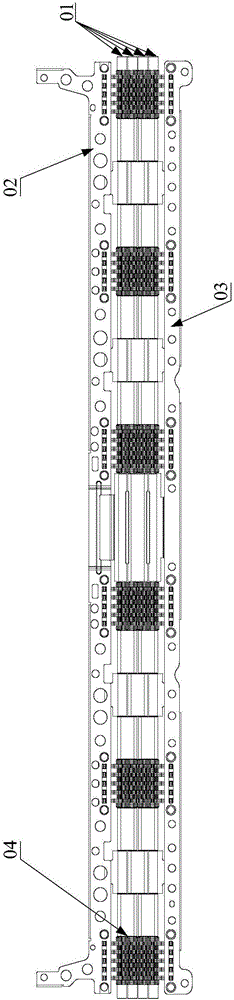
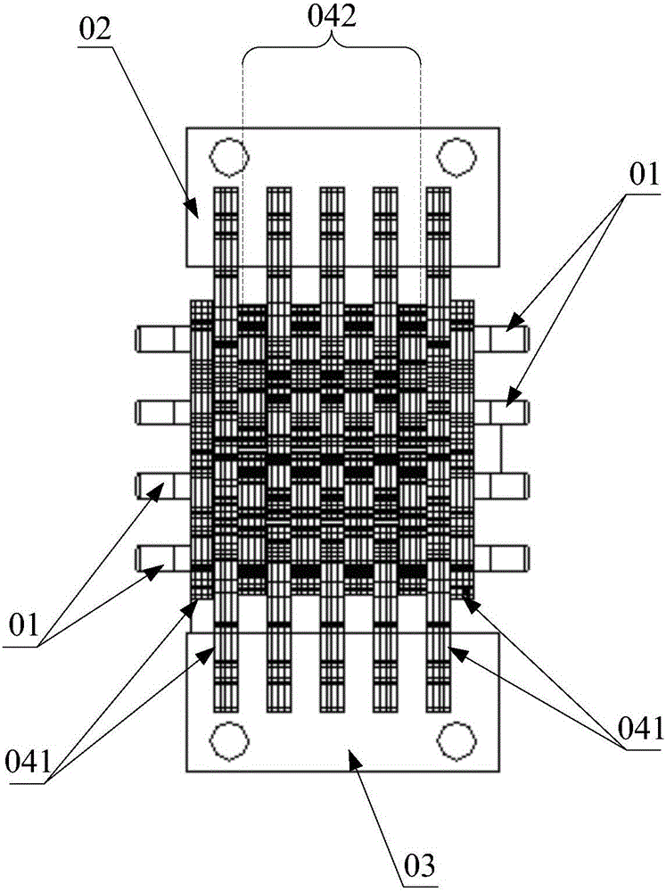
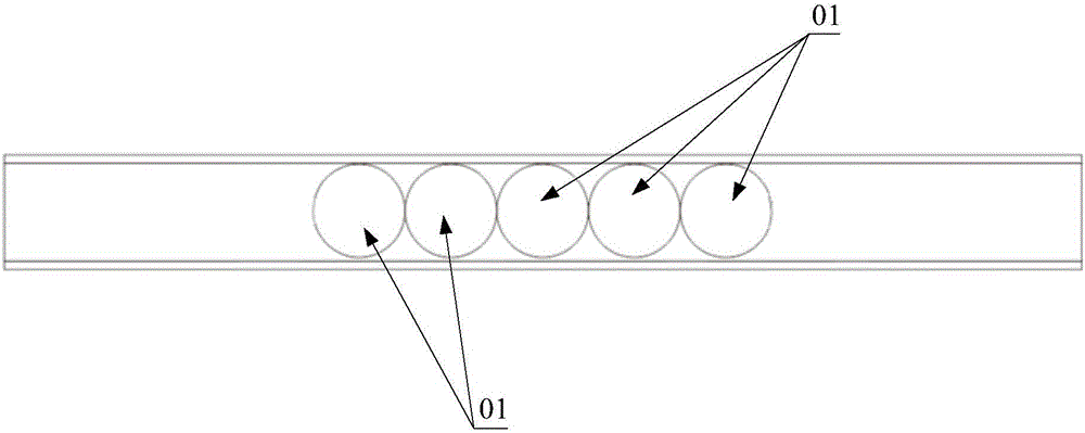
[0037] The invention provides a watch chain shaft mechanism, which can better cooperate with the appearance of other parts of the electronic equipment after it is installed on the electronic equipment, improves the consistency of the appearance of the electronic equipment, and makes the appearance of the electronic equipment more beautiful.

[0038] The following will clearly and completely describe the technical solutions in the embodiments of the present invention with reference to the accompanying drawings in the embodiments of the present invention. Obviously, the described embodiments are only some, not all, embodiments of the present invention. Based on the embodiments of the present invention, all other embodiments obtained by persons of ordinary skill in the art without making creative efforts belong to the protection scope of the present invention.

[0039] like Figure 5-Figure 10 As shown, the watch chain shaft mechanism provided by the embodiment of the present inv...


PUM


Abstract

The invention discloses a watch chain shaft mechanism. The watch chain shaft mechanism comprises a plurality of rotation shafts and a plurality of hinge mechanisms, wherein the plurality of rotation shafts are arranged in parallel, the plurality of hinge mechanisms are arranged on the rotation shafts, two arbitrary adjacent rotation shafts are connected through the hinge mechanism, and wrapping layers covers surfaces of all hinge mechanisms. In the watch chain shaft mechanism provided by the embodiment of the invention, the rotation shafts which are arranged adjacent to each other are connected in a pairwise manner by the hinge structures, so that the two rotation shafts which are connected to each other only rotate relative to each other, no displacement change is generated, the relative displacement change among the rotation shafts is generated only between different combinations, no interference is generated on normal working of the rotation shafts by the wrapping layers wrapping the external parts of the rotation shafts, all outer surfaces of the watch chain shaft mechanism can be covered and decorated on the premise of ensuring the normal working of the watch chain shaft mechanism, the appearance consistency of an electronic device can be improved, and the appearance of the electronic device is more attractive. The invention also provides the electronic device with the above watch chain shaft mechanism.

Description

technical field [0001] The present invention relates to the technical field of electronic equipment, and in particular to a watch chain shaft mechanism. The invention also relates to an electronic device capable of turning over and opening and having the above-mentioned watch chain shaft mechanism. Background technique [0002] In the existing electronic devices such as notebook computers and mobile phones, the screen part and the host part which can be opened and closed relative to each other are all connected by a rotating shaft mechanism. [0003] At present, there are many types of rotating shaft mechanisms, and the watch chain shaft mechanism is more and more popular because it can realize the 360-degree linkage flip of the screen part and the host part. like figure 1 As shown, the watch chain axis mechanism includes multiple (generally at least three) rotating shafts 01 arranged in parallel. Among the two outer rotating shafts located on the outermost side, one is con...

Claims


Application Information

Patent Timeline
IPC IPC(8): H05K5/02F16C11/04
CPCH05K5/0226F16C11/04
Inventor 杨峰尤德涛
Owner LENOVO (BEIJING) CO LTD
Why Eureka
Try Eureka