
A structure of igbt inverter welding machine with two welding function modules

An inverter welding machine and functional module technology, applied in welding equipment, arc welding equipment, manufacturing tools, etc., can solve the problems of low sales price, low reliability and high cost, achieve good adaptability, meet high efficiency and low cost The effect of production, high reliability

Active Publication Date: 2017-12-22
ZHEJIANG KENDE MECHANICAL & ELECTRICAL
View PDF6 Cites 0 Cited by
  • Summary
  • Abstract
  • Description
  • Claims
  • Application Information

AI Technical Summary

Problems solved by technology

However, for this type of welding machine, different circuits, circuit boards and complete machine structure designs, different control principles and methods, layout and connection methods of circuit boards and complete machines, or different degrees of complexity of connection, the performance and reliability of their products , production process and production process are also completely different
These will affect the production cost and sales of the product and the market competitiveness of the product
For example, a welding machine with poor performance will have poor welding effect, and users will not like it; if the reliability is low, the welding machine will often break down, and dealers will no longer sell such products; if the cost is high, the sales price cannot be too high. Low
In this way, it will also affect the promotion and sales of products.

Method used

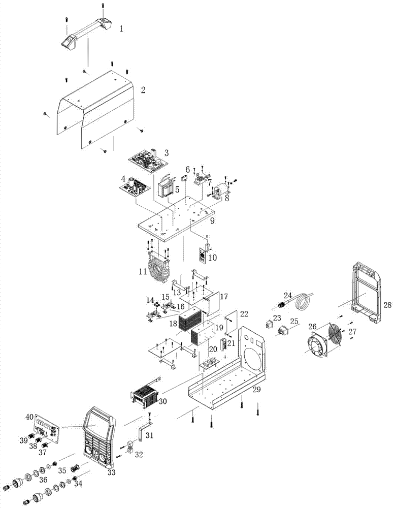

Image

  • A structure of igbt inverter welding machine with two welding function modules
  • A structure of igbt inverter welding machine with two welding function modules
  • A structure of igbt inverter welding machine with two welding function modules

Examples


Embodiment Construction

[0029] The wire feeding mechanism, the welding torch and the protective gas source part involved in the present invention mainly include the wire feeding mechanism, the gas shielded welding torch and the protective gas cylinder part. These parts are standard auxiliary parts in addition to the welding machine of the present invention. It is also available in the market. This patent specification only illustrates the relationship between these parts and the present invention. During gas shielded welding, the plug part of the control wire on the wire feeding mechanism is connected to the aviation socket (35, the number represents the attachment) on the front panel of the welding machine. figure 1 the part code in the , the same below) for the corresponding connection. The welding gun is matched and connected with the welding gun seat of the wire feeding mechanism. The wire is mounted on the wire spool shaft of the wire feed mechanism. The welding wire can be extended from the...


PUM


Abstract

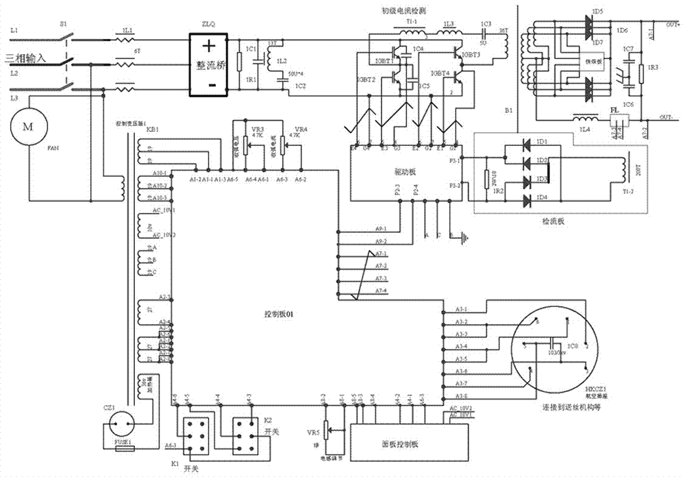
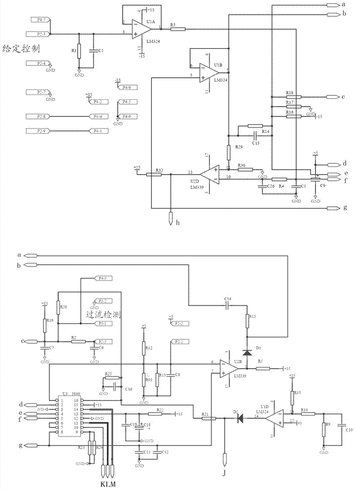
The invention relates to a structure of an IGBT inverter welding machine with two welding functional modules. The structure comprises an outer housing and an inner circuit board; the circuit board mainly comprises six parts which are separately a drive plate, a control panel, a current detecting plate, an IGBT plate, a fast recovery circuit board and a panel control board; the control panel is connected to the panel control board, a control transformer and the drive plate; the control transformer is used for supplying power to the control panel; the drive plate is connected to the control panel, the IGBT plate and the current detecting plate; and under the action of the control panel, the drive plate generates a drive signal which can reliably drive each IGBT to work, so that stable operation of an inverter circuit is guaranteed. According to the structure, the performance problem, the reliability problem, the production efficiency problem and the manufacturing and transporting cost problem of multifunctional welders are solved very well by adopting a control circuit system consisting of a two-chip micro processor, a single-chip micro processor and the like and optimizing the structural design of a welding machine control circuit, the structural design of a circuit board and the structural design of each part, so that market competitiveness of products is improved.

Description

technical field [0001] The invention relates to a structure of an IGBT inverter welding machine with two welding function modules, and belongs to the technical field of inverter welding machines. technical background [0002] At present, the competition in the market of inverter MIG / MAG gas shielded welding machine products is very fierce, which is not only reflected in the advanced nature and advantages of technology, but also depends on the design of the function and structure of the welding machine to a large extent. [0003] In domestic and foreign markets, the rated current of IGBT tube inverter MIG / MAG gas shielded welding machines is usually at the level of 140~500A (load duration 100~35%). If the current is less than 260A, the IGBT usually adopts a single tube. However, if the current is greater than 260A, the IGBT usually adopts the module. For such welding machine products, some products only have a single MIG / MAG gas shielded welding function, and their applicat...

Claims


Application Information

Patent Timeline
Patent Type & Authority Patents(China)
IPC IPC(8): B23K9/10
CPCB23K9/105
Inventor 陈权魏继昆陈法庆朱宣辉朱宣东
Owner ZHEJIANG KENDE MECHANICAL & ELECTRICAL
Learn More