
Clamp structure with three-dimensional machining function

A technology of functional fixtures and clamping mechanisms, which can be used in wood processing appliances, workbenches, manufacturing tools, etc., and can solve problems such as damage

Active Publication Date: 2016-11-16
丰县正海金属科技有限责任公司
View PDF7 Cites 1 Cited by
  • Summary
  • Abstract
  • Description
  • Claims
  • Application Information

AI Technical Summary

Problems solved by technology

[0003] In the prior art, during wood processing, because the wood itself is soft, it is easy to be damaged due to too tight clamps.

Method used


Image

  • Clamp structure with three-dimensional machining function
  • Clamp structure with three-dimensional machining function
  • Clamp structure with three-dimensional machining function

Examples


Embodiment Construction

[0034] The present invention will be described in further detail below in conjunction with the embodiments given in the accompanying drawings.

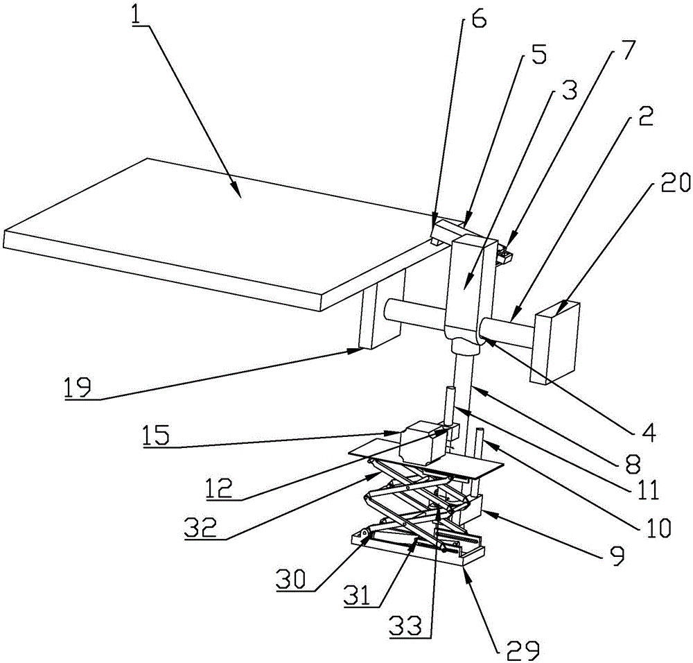
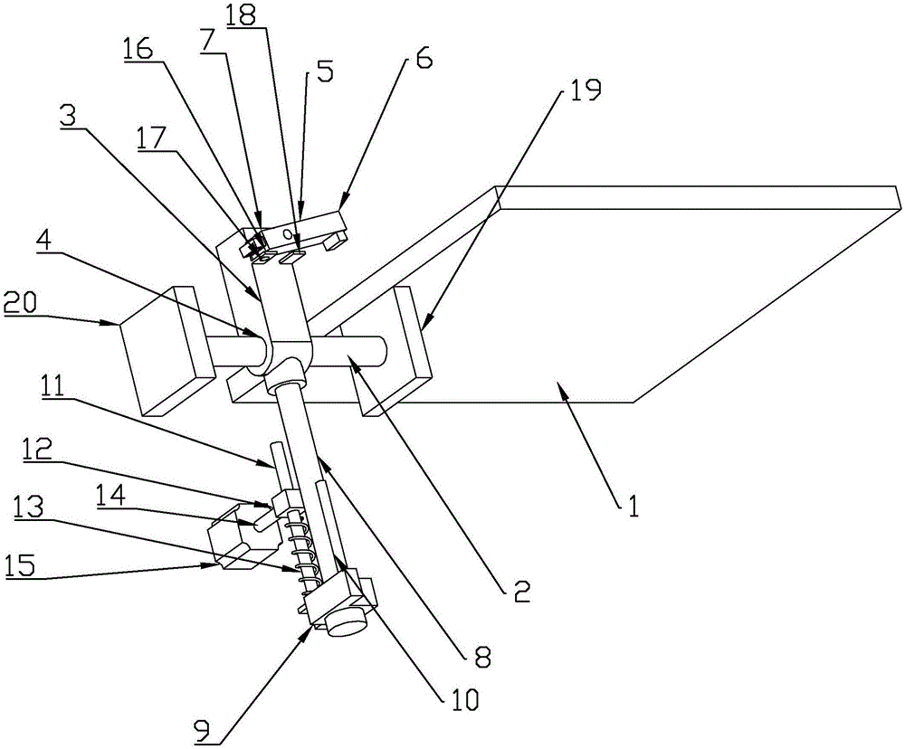
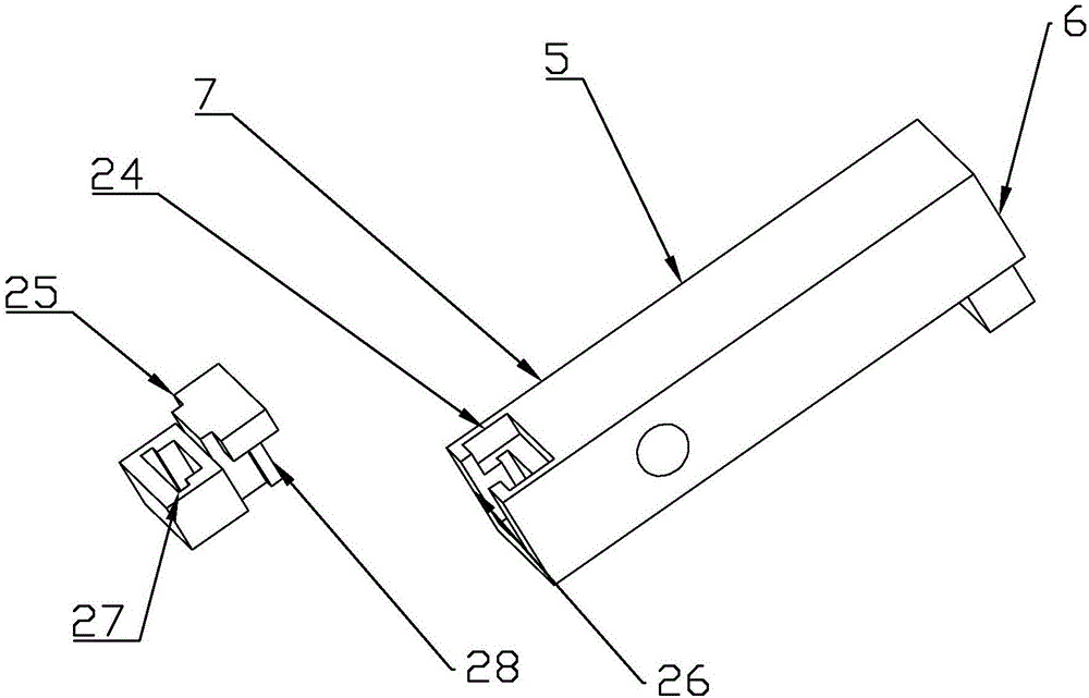
[0035] refer to Figures 1 to 7 As shown, a fixture structure with a three-dimensional processing function in this embodiment includes a mounting table 1 for placing planks, a clamping mechanism for clamping the planks, and a track bar 2 for the movement of the clamping mechanism. The clamping mechanism Including the first slider 3, the first slider 3 is provided with a slide hole 4, the track bar 2 passes through the slide hole 4, so that the first slider 3 is slidably connected to the track bar 2, the first track bar 2 A slider 3 is hinged with a clamping block 5, the clamping block 5 is provided with a clamping end 6 and a gravity end 7, the weight of the gravity end 7 is greater than that of the clamping end 6, and the clamping end 6 faces the installation The table 1 is set, the first slider 3 is provided with a slider 8, the sl...


PUM


Abstract

The invention discloses a clamp structure with a three-dimensional machining function. When the distance is shortened, under the action of driving force of a rotary mechanism, the end, close to a second slide block, of a linkage rod moves towards a third slide block. When the distance is increased, under the action of a first spring, the end, close to the second slide block, of the linkage rod moves away from the third slide block. When the first slide block slides to a mounting table to abut against the mounting table, under the limiting action of the mounting table, the first slide block cannot continue to move and then cannot continue to move on a rail strip, and at the same time, the rotary mechanism continues to rotate, so that the second slide block moves on a slide bar so as to be close to the first slide block; an ejector rod arranged on the second slide block moves towards a clamping block at the same time, finally, the ejector rod abuts against the gravity end, the clamping end moves towards the mounting table, and therefore the clamping end clamps a board arranged on the mounting table. In this way, the board is prevented from being damaged by too large clamping force in the clamping process.

Description

technical field [0001] The invention relates to a fixture, more specifically to a fixture structure with three-dimensional processing function. Background technique [0002] The device used to fix the processing object in the process of mechanical manufacturing so that it occupies the correct position to accept construction or inspection, also known as fixture. In a broad sense, any process in the process, the device used to install the workpiece quickly, conveniently and safely, can be called a fixture. Such as welding fixtures, inspection fixtures, assembly fixtures, machine tool fixtures, etc. Among them, machine tool fixtures are the most common, often referred to as fixtures. When processing a workpiece on a machine tool, in order to make the surface of the workpiece meet the technical requirements such as the size, geometric shape, and position accuracy with other surfaces specified in the drawing, the workpiece must be installed (positioned) and clamped (clamped) be...

Claims


Application Information

Patent Timeline
Patent Type & Authority Applications(China)
IPC IPC(8): B27C9/00B25H1/08
CPCB25H1/08B27C9/00
Inventor 李彬彬
Owner 丰县正海金属科技有限责任公司
Learn More