
Device for preventing fasteners from being twisted during installation of elastic bars

A technology of fasteners and elastic strips, applied in the field of rail transit, to simplify the adjustment process of fastener spacing, convenience and accuracy, and improve overall stability.

Active Publication Date: 2016-11-16
洛阳双瑞橡塑科技有限公司
View PDF5 Cites 0 Cited by
  • Summary
  • Abstract
  • Description
  • Claims
  • Application Information

AI Technical Summary

Problems solved by technology

[0003] In view of the above-mentioned prior art, when installing the fastener clips, due to the asymmetry of the fastener force and the relative lightness of the fastener, a large torsional moment will be generated on the fastener, thereby causing vibration between the vibration-damping fastener and the rail. There is a problem of complete hidden danger due to twisting, the present invention provides a device for preventing the twisting of fastener clips when they are installed

Method used


Image

  • Device for preventing fasteners from being twisted during installation of elastic bars
  • Device for preventing fasteners from being twisted during installation of elastic bars
  • Device for preventing fasteners from being twisted during installation of elastic bars

Examples


Embodiment 1

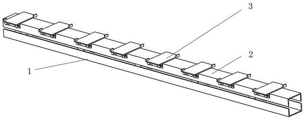
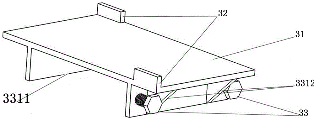
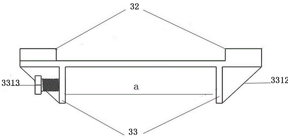
[0028] Such as figure 1 , figure 2 , image 3 As shown, the device body 1 includes a support base 2 and a plurality of bearing grooves 3 for fixing the fastener bottom plate 4. The support base 2 is a large-mass structure parallel to the rail of the fastener clip to be installed. The length of the base 2 is not less than the length of the fastener rail to be installed; the plurality of bearing grooves 3 are fixedly arranged on the supporting base 2; the bearing grooves 3 are provided with a bearing plate 31, a shoulder 32 and a connecting mechanism 33, There are at least two shoulders 32, which are respectively arranged on both sides of the top of the bearing plate 31. The width of the inner cavity formed by the shoulders 32 is equal to the width of the fastener bottom plate 4. The bearing groove 3 passes through the connecting mechanism 33. Fixedly connected with the support base 2, the bearing plate 31 has the same shape and size as the fastener base plate 4, and the sho...

Embodiment 2

[0032] Figure 6 , Figure 7A schematic structural view of Embodiment 2 of the present invention is given. The main structure of this embodiment is the same as that of Embodiment 1. In this embodiment, the supporting base 2 of the device body 1 is a steel rail with a large mass, and the bearing groove 3 There are two symmetrical shoulders 32, and the connection mechanism 33 between the bottom of the carrying tank 3 and the support base 2 is designed according to the shape of the rail, and is composed of a fixed baffle 3321, a locking mechanism 3322 and a tightening screw 3323. There are at least two baffles 3321, both of which are arranged on the bottom of the bearing plate 31, and are clamped and fixed on the top of the support base 2. The locking mechanism 3322 is clamped at the middle of the support base 2, and is tightened by a screw rod 3323 Fixed and locked; when in use, put the bearing groove 3 from the end of the rail on one side and place it on the support base 2, se...


PUM


Abstract

The invention relates to a device for preventing fasteners from being twisted during installation of elastic bars. The device comprises a support base and multiple bearing grooves used for fixing fastener baseplates. The multiple bearing grooves are fixedly arranged in the support base; each bearing groove comprises a bearing flat plate, at least two bumping shoulders and a connecting mechanism, the bumping shoulders are arranged at the two sides of the tops of the corresponding bearing flat plates, the width of an inner cavity formed by each at least two bumping shoulders is equal to the width of the corresponding fastener baseplate, and the bearing grooves are fixedly connected with the support base through the corresponding connecting mechanism. According to the device, the support base and the bearing grooves for the fastener baseplates are arranged, thus the mass of the fastener baseplates is increased in the whole when the elastic bars are pulled in, the twisting moment generated during installation of the elastic bars is overcome through the whole dead weight, and the secondary twisting moment of a steel rail and the fasteners relative to jacking devices is solved.

Description

technical field [0001] The invention relates to the technical field of rail transit, in particular to a device for preventing twisting of fastener clips during installation. Background technique [0002] In recent years, domestic urban rail transit systems have developed rapidly, providing great convenience for people's travel. The fastener is an important part of the track structure, which realizes the connection between the rail and the track bed, and supports and fixes the rail at the same time. The construction method of the track structure is the ground-assembled rail row structure, which is transported to the construction site for geometric adjustment of the track and pouring of concrete. The top-down construction method is adopted in the assembly of the rail row, that is, the connection between the vibration-damping fastener and the rail is firstly installed, that is, a certain length of rail and the vibration-damping fastener are installed as a whole. Then install ...

Claims


Application Information

Patent Timeline
Patent Type & Authority Applications(China)
IPC IPC(8): E01B9/62E01B9/38
CPCE01B9/38E01B9/62
Inventor 段勇奇王彦飞瞿连辉李强
Owner 洛阳双瑞橡塑科技有限公司
Learn More