A valve actuator based on gas-hydraulic combined spring

A technology of valve actuator and combined spring, which is applied in the direction of valve details, valve device, valve operation/release device, etc., can solve the problems of easy fatigue failure, troublesome installation, heavy quality, etc., and achieve safety, reliability, convenient installation, Safe to use

Active Publication Date: 2018-10-19
CHENGDU MAIKESEN FLUID CONTROL EQUIP
View PDF5 Cites 0 Cited by
  • Summary
  • Abstract
  • Description
  • Claims
  • Application Information

AI Technical Summary

Problems solved by technology

[0013] The purpose of the present invention is to overcome the deficiencies of the prior art, to provide a valve actuator based on a gas-hydraulic combined spring, and to solve the problem of using a traditional spring cylinder of the existing valve actuator, which is heavy in mass, large in volume, takes up space, and is prone to fatigue failure. Trouble with installation

Method used


Image

  • A valve actuator based on gas-hydraulic combined spring
  • A valve actuator based on gas-hydraulic combined spring
  • A valve actuator based on gas-hydraulic combined spring

Examples


Embodiment 1

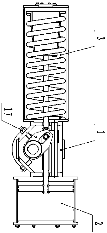
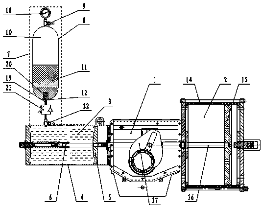
[0042] Such as figure 2As shown, a valve actuator based on a gas-hydraulic combined spring includes an actuator 1 and a power cylinder 2. The power cylinder 2 adopts a pneumatic cylinder, and the pneumatic cylinder is installed on the side of the actuator 1. The installation of the pneumatic cylinder and the actuator 1 The connection mode is the same as that of the prior art, and the structure of the actuator 1 also adopts the existing structure. The other side of the actuator 1 is provided with a gas-hydraulic combination spring cylinder 3, which includes a spring cylinder body 4 and a spring piston 5. And the spring piston rod 6, the spring piston rod 6 is arranged in the spring cylinder 4, the spring piston 5 is fixedly arranged on the spring piston rod 6, the spring cylinder 4 is provided with a gas-liquid combination spring device 7, and the gas-liquid combination spring device 7 Including a pressure vessel tank 8, the upper end of the pressure vessel tank 8 is provided ...

Embodiment 2

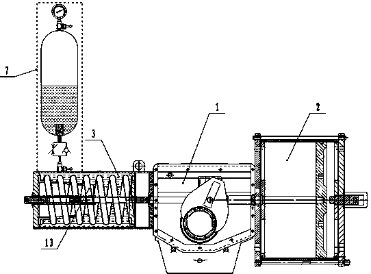
[0058] Such as image 3 As shown, a valve actuator based on a combined gas-hydraulic spring, based on Embodiment 1, a spring 13 is provided on the spring piston rod 6 at the rear end of the spring piston 5 . When the pneumatic cylinder takes in air, the piston 15 of the pneumatic cylinder pushes the piston rod 16 to move forward, and the piston rod 16 pushes the shift fork 17 to open the valve. At the same time, the gas-liquid combined spring device 7 and spring 13 are compressed. The piston 15 pulls the piston rod 16 to retract under the joint action of the gas-hydraulic combination spring device 7, the spring 13 and the pneumatic cylinder, and the piston rod 16 drives the shift fork 17 to reversely move to close the valve.

[0059] On the basis of the original spring cylinder, the front end of the spring in the spring cylinder is provided with a spring piston linked with the spring piston rod. "Device" can greatly reduce the installation size of the original spring cylinder...

Embodiment 3

[0061] Such as Figure 4 As shown, a valve actuator based on a gas-hydraulic combined spring. On the basis of Embodiment 1, the power cylinder 2 adopts a hydraulic cylinder. When the hydraulic cylinder enters oil, the piston 15 of the hydraulic cylinder pushes the piston rod 16 to move forward, and the piston The rod 16 pushes the shift fork 17 to open the valve. At the same time, the gas-hydraulic combination spring device 7 and the spring 13 are compressed. The piston rod 16 retracts, and the piston rod 16 drives the shift fork 17 to reversely move to close the valve.


PUM


Abstract

Disclosed is a valve actuator based on a gas-fluid composite spring, the valve actuator comprising an actuator (1) and a power cylinder (2). The power cylinder (2) is mounted on one side of the actuator (1), and a gas-fluid composite spring cylinder (3) is provided on the other side of the actuator (1). The gas-fluid composite spring cylinder (3) comprises a spring cylinder body (4), a spring piston (5), and a spring piston rod (6). The spring piston rod (6) is provided within the spring cylinder body (4). The spring piston (5) is fixedly arranged on the spring piston rod (6). A gas-fluid composite spring device (7) is disposed above the spring cylinder body (4). The gas-fluid composite spring device (7) comprises a pressure vessel (8), and a gas inlet (9) is provided at an upper end of the pressure vessel (8). An upper portion and lower portion within the pressure vessel (8) are respectively a compressed gas chamber (10) and a hydraulic fluid chamber (11). The compressed gas chamber (10) is filled with a compressed gas, and the hydraulic fluid chamber (11) is filled with a hydraulic fluid. A hydraulic fluid outlet (12) is provided at a lower end of the pressure vessel (8).

Description

technical field [0001] The invention relates to the field of a valve actuator, in particular to a valve actuator based on a gas-hydraulic combined spring. Background technique [0002] A valve actuator is a driving mechanism that realizes the opening or closing of a valve. Its structure generally includes a power actuator, an actuator box, and a spring cylinder. At the same time, when the control system loses power or air source, the single-acting actuator can automatically reset and drive the valve to the pre-designed fail-safe position, thereby minimizing the potential danger of the entire device. Single-acting actuators usually use the energy stored in compressed metal springs, UPS emergency power supply, or accumulator tanks, and other pre-stored energies such as weights to drive the actuator. Among them, the compressed metal spring is the most widely used actuator driving method. [0003] An actuator spring cylinder is a mechanical assembly that utilizes the elasticit...

Claims


Application Information

Patent Timeline
Patent Type & Authority Patents(China)
IPC IPC(8): F16K31/12F16K37/00
CPCF16K31/124
Inventor 王正权
Owner CHENGDU MAIKESEN FLUID CONTROL EQUIP
Why Eureka
Try Eureka