Drive device based on gas-liquid combination spring and valve actuator

A technology of combined spring and driving device, which is applied in the direction of valve operation/release device, valve device, valve details, etc., can solve the problems of easy fatigue failure, troublesome installation, large volume, etc., and achieve safety and reliability, convenient installation, and reduce The effect of using

Active Publication Date: 2016-11-09
CHENGDU MAIKESEN FLUID CONTROL EQUIP
View PDF5 Cites 8 Cited by
  • Summary
  • Abstract
  • Description
  • Claims
  • Application Information

AI Technical Summary

Problems solved by technology

[0013] The purpose of the present invention is to overcome the deficiencies of the prior art, to provide a hydraulic valve actuator based on a gas-hydraulic combined spring, and to solve the p...

Method used


Image

  • Drive device based on gas-liquid combination spring and valve actuator
  • Drive device based on gas-liquid combination spring and valve actuator
  • Drive device based on gas-liquid combination spring and valve actuator

Examples


Embodiment 1

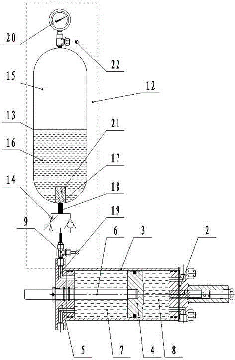
[0042] Such as figure 2 As shown, a driving device based on a gas-hydraulic combined spring in the present invention includes a power cylinder 2, the power cylinder 2 adopts a hydraulic oil cylinder, and the power cylinder 2 is provided with a gas-hydraulic combined spring device 12, and the gas-hydraulic combined spring device 12 includes a pressure vessel Tank 13, the upper end of the pressure vessel tank 13 is provided with a gas input port 22, the upper and lower parts of the pressure vessel tank 13 are respectively a compressed gas chamber 15 and a hydraulic oil chamber 16, the compressed gas chamber 15 is filled with compressed gas, and the hydraulic oil chamber 16 Filled with hydraulic oil, the lower end of the pressure vessel tank 13 is provided with a hydraulic oil outlet 17 .

[0043] The power cylinder 2 includes a cylinder body 3, a piston 4, a cylinder seat 5 and a piston rod 6. The inner cavity of the cylinder body 3 at the front end of the piston 1 is the pisto...

Embodiment 2

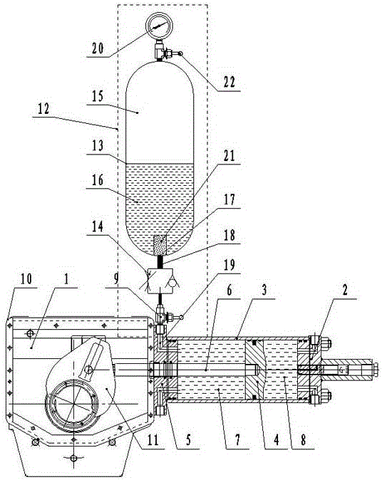
[0047] Such as image 3 As shown, the present invention is a driving device based on a gas-hydraulic combined spring. On the basis of Embodiment 1, the power cylinder 2 adopts an air cylinder, and the cylinder base 5 is provided with a hydraulic oil passage 19 communicating with the piston front cylinder 7. The hydraulic oil outlet 17 communicates with the piston front cylinder 7 through the oil pipe 18 and the hydraulic oil passage 19; when the air cylinder is inhaled, the piston 4 of the cylinder pushes the piston rod 6 to move forward, and at the same time, the gas-hydraulic combined spring device 12 is compressed , When the cylinder is deflated, the piston 4 pulls the piston rod 6 to retract under the joint action of the gas-liquid combination spring device 12 and the cylinder.

Embodiment 3

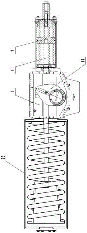
[0049] Such as Figure 4 As shown, a valve actuator of the present invention includes an actuator 1 and a hydraulic cylinder. The hydraulic cylinder includes a cylinder body 3, a piston 4, a cylinder seat 5 and a piston rod 6. The inner cavity of the cylinder body 3 at the front end of the piston 1 is the front cylinder of the piston. 7. The inner cavity of the cylinder body 3 at the rear end of the piston 4 is the piston rear cylinder 8, and the hydraulic cylinder is installed on the casing 10 of the actuator 1 through the cylinder base 5, and the piston rod 6 of the hydraulic cylinder is connected to the dial of the actuator 1. Fork 11 linkages. The hydraulic oil cylinder is provided with a gas-liquid combination spring device 12, and the gas-liquid combination spring device 12 includes a pressure vessel tank 13, and the upper end of the pressure vessel tank 13 is provided with a gas input port 22, through which gas can be injected into the pressure vessel tank 13. Input hi...


PUM


Abstract

The invention discloses a drive device based on a gas-liquid combination spring and a valve actuator. The drive device comprises the actuator and a power cylinder. The power cylinder is installed on the actuator and provided with the gas-liquid combination spring. The gas-liquid combination spring comprises a pressure container tank. A gas input opening is formed in the upper end of the pressure container tank. A compressed gas cavity is formed in the upper portion in the pressure container tank, and a hydraulic oil cavity is formed in the lower portion of the pressure container tank. The compressed gas cavity is filled with compressed gas. The hydraulic oil cavity is filled with hydraulic oil. A hydraulic oil outlet is formed in the lower end of the pressure container tank. The gas-liquid combination spring with the same function replaces a traditional metal spring or a metal spring cylinder only serving as a valve actuator. The structural design, the manufacturing technology, site replacement, breakdown maintenance, the actuator drive valve application efficiency and the work reliability of the gas-liquid combination spring are improved greatly, and the manufacturing cost and the installing work difficulty are reduced greatly.

Description

technical field [0001] The invention relates to the field of a valve actuator, in particular to a driving device and a valve actuator based on a gas-liquid combined spring. Background technique [0002] The actuator is a control actuator for opening and closing the valve. Its structure generally includes a power actuator, an actuator box, and a spring cylinder. It is generally used in emergency working conditions and pipeline application systems. , At the same time, when the control system loses power or air source, the single-acting actuator can automatically reset and drive the valve to the pre-designed fail-safe position, thereby minimizing the potential danger of the entire device. Single-acting actuators usually use the energy stored in compressed metal springs, UPS emergency power supply, or accumulator tanks, and other pre-stored energies such as weights to drive the actuator. Among them, the compressed metal spring is the most widely used actuator driving method. ...

Claims


Application Information

Patent Timeline
IPC IPC(8): F16K31/122F16K37/00
CPCF16K31/122F16K37/00F16K31/1221
Inventor 王正权
Owner CHENGDU MAIKESEN FLUID CONTROL EQUIP
Why Eureka
Try Eureka